Title Page
-
Site / Address:
-
Technician:
-
Conducted on
-
Serial number:
-
Charger version:
-
Customer:
-
Vehicle:
1. Photos of the charger
-
Photo of charger
-
Photo inside of charger body
-
Photo inside of front of charger
-
Photo inside of front of charger
-
Photo of cover
-
Photo of body
-
Photo of the Serial number, if visuable
WallBox Checks
-
2.1 Is the status LED on?<br>(Check electric installation and Molex, also if <br>there is any LED on inside)
-
2.2 What is the color of the status LED? (review section 5.2. of the Annex)
- Yellow
- Green
- Blue
- Orange
- Red
- Turquoise
- LED off
- Blinking
-
2.3 Is possible to synchronize with Wallbox APP?
-
2.4 Charger appears on nearby devices? (check in the Bluetooth settings of the mobile (Android) or BLE Scanner 4.0 App (Apple))
-
2.5 Is it connected to internet?
-
2.6 Is the WallBox making any noise or buzzing?
-
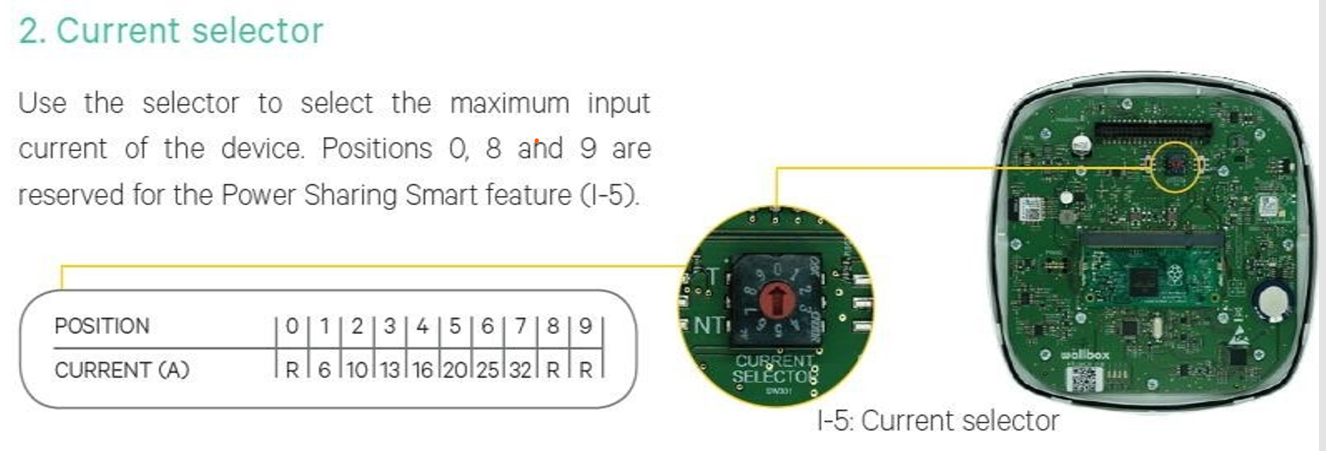
2.7 In what position is the current selector?
- 0
- 1
- 3
- 4
- 5
- 6
- 7
- 8
- 9
-
Current selector pic
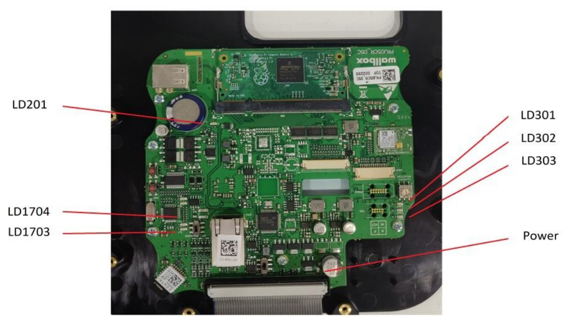
2.8 In which state are the LEDs on the carrier
-
In which state are the LEDs on the Carrier (CR)
LED Lights
-
Power LED (Normally on)
-
LED301 RED LED (EPROM) (Normally blinking)
-
LD302 RED LED (EPROM) (Normally off, if blinking count the number of blinks and make a video)
-
LD303 RED LED (EPROM) (Normally blinking)
-
LED 201 GREEN (RPI) (Normally slow blink. When fix check the RPI)
In which position are the switches on the Carrier (CR)?
-
CAN BUS
-
RS485 (Does not apply for Rev A)
Electric Installation
Electric Installation
-
Single-Phase
-
Bi-Phase
-
Tree-Phase
-
IT
-
TT/TN
-
MCB (A)
-
RCD (Type)
-
Other:
-
Earth resistance of the charger instalation: (Some EV car models do not accept more than 150 Ohm). Ohm
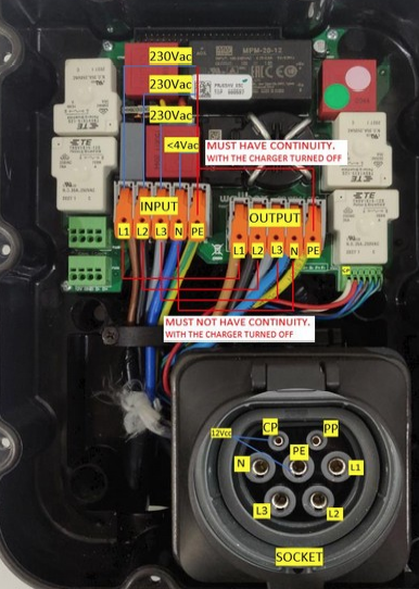
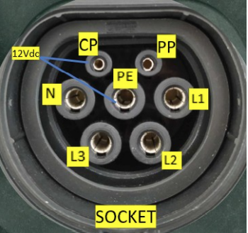
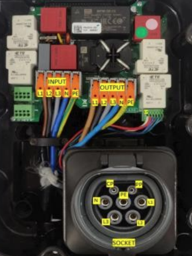
Voltage measurements on the charger: (review section 5.1. of the Annex) The measurements in 3.2.1 and 3.2.2 must be carried out with power supply to the charger!
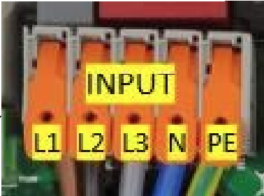
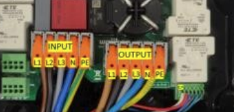
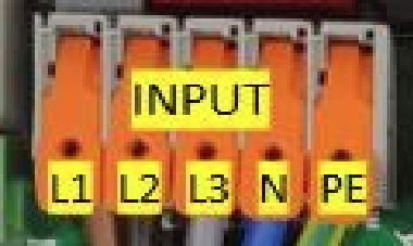
1 Measurements on the power supply of the charger.
-
N-PE (0Vac)
-
N-L1 (230Vac)
-
N-L2 (230Vac)
-
N-L3 (230Vac)
-
PE-L1 (230Vac)
-
PE-L2 (230Vac)
-
PE-L3 (230Vac)
-
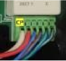
CP-PE (12Vdc) (12V in case no error is detected by the charger, as it would measure -12V)
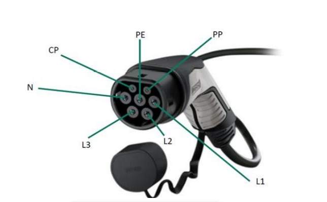
2 EVgun mesures: (connect a cable to the charger) (review section 5.3. of the Annex)
-
N-PE (0Vac)
-
N-L1 (230Vac)
-
N-L2 (230Vac)
-
N-L3 (230Vac)
-
PE-L1 (230Vac)
-
PE-L2 (230Vac)
-
PE-L3 (230Vac)
-
CP-PE (12Vdc) (12V in case no error is detected by the charger, as it would measure -12V)
Continuity measurements on the charger
-
The measurements in 3.3.1 and 3.3.2 must be carried out without power supply to the charger!
-
-
-
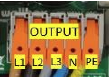
1 Verification of relays, must be measured between the supply connections and the terminals of the hose output: There must be no continuity in the lines, only on the ground (PE).
-
Continuity L1 input - L1 output:
-
Continuity L2 input - L2 output:
-
Continuity L3 input - L3 output:
-
Continuity N input - N output:
-
Continuity PE input - PE output:
2 EVgun cable continuity: should be measured between the EVg
-
-
-
-
-
Continuity L1 EVg - L1 output:
-
Continuity L2 EVg - L2 output:
-
Continuity L3 EVg - L3 output:
-
Continuity N EVg - N output:
-
Continuity PE EVg - PE output:
-
Continuity CP EVg - CP output:
-
More details of the place of installation (eg, it is at the end of the line, there is heavy machinery nearby, it is located in an industrial area, ...)


