")


Information
-
Name of Site
-
Builder
-
Floor Level / Location on site inspection occured
-
Site Location / Address
-
Auditor
-
Conducted on
-
Company Name here.........
Phone: 1300 .............
Address: here..................
ABN here 123456789

Inspection of Existing Area (Audit):
Inspection overview:
-
General Description of Area Inspected:
-
Add Photo:
Item #
-
Inspection:
-
Action by date:
- Specify date
- Immediate
- 1 week
- 2 weeks
- 1 month
- On going
- No Action required
-
Select date
-
Add Photo:
-
Are there any issue present? or, Does the existing substrate require any surface preparation prior to installation of a new membrane to comply with the requirements of Australian Standards 4654.2-2012 & 3740—2010 & Supplier Application method statements?
-
Comments:
-
Does this relate to any of the following items:
- Curingtimes & Moisture Content of Concrete
- Contaminants and issues affecting bonding
- Existing Membrane located in area
- Existing membrane bubbling / pinholes
- Water present in the substrate
- Caulking not compatible - Silicon etc installed by other trades
- Fire Caulking
- Substrate finish suitable for membrane - Concrete
- Substrate finish suitable for membrane - Blockwork
- Substrate finish suitable for membrane - Lightweight Timber structures
- Post Tension Pockets, Grout Tubes etc
- Work area not clean and clear of any building Debris, ponding water, Other Trades, other items
- Exclusion / Drop Zone
- Weather - Rain and Temperature
- Hobs and Up-turn heights
- Membrane Fillets
- Falls / Drainage
- Floor Wastes
- DDA requirement - Grate at door threshold
- Pipe Penetrations
- Flexible Conduits
- Bunched Pipes / Conduits
- Unsealed conduits
- Pipes hard against walls and hobs - not able to properly detail
- Overflows
- Fixings & Penetrations through the membrane
- Planter Box Overflow inspection risers
- Weep holes
- Dividing Walls, Landscape Walls, Retaining walls - ontop of membranes
- Construction Joints
- Sheet joint laps facing the wrong direction
- Sheet Laps width not compliant
- Pressure flashing not present or installed correctly
- Upturn Heights of Membrane
- Handrails
- Screed MPA / strength
- Other Finishes already installed
- Protection not installed over membrane - ie protection board under drainage cell and soil etc
- Double layer slip sheet not installed
- Damage done to membrane
- Efflorescence and Calcification
- Blocked Drainage system
- Debris and Overburden Creating blockage of Drainage
- Double layer Slip Sheet over membrane
- Compatibility issues between products
- Pin Holing / Outgassing in membrane
- Mould present
- Cracking in substrate
- Other items
-
Curing times of substrates:
All concrete and masonry should be cured for 28 days prior to application of the membrane - as per supplier’s requirements on their Technical Data Sheets to meet warranty conditions.
AS 4654.2 – 2012 states:
“moisture content in the substrate should be under 8.0% for most membranes (5% or less for Spray applied Polyurea membranes). If a Waterproof membrane is applied to a damp/green substrate there is a high risk the application will either de-bond or become fractured due to the force of the moisture trying to evaporate from the substrate. When there is trapped moisture in the substrate membranes can show signs of blistering or bubbling known in the industry pin holing, and delamination.”
-
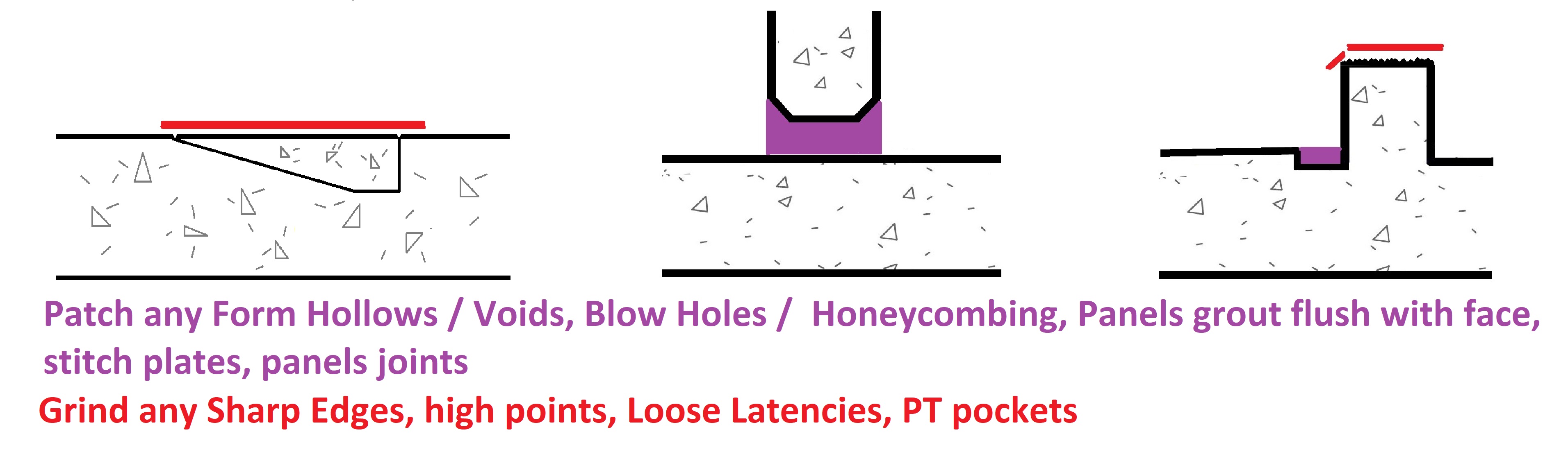
Substrate surface patching / preparation required prior to membrane application.
To be done by others.
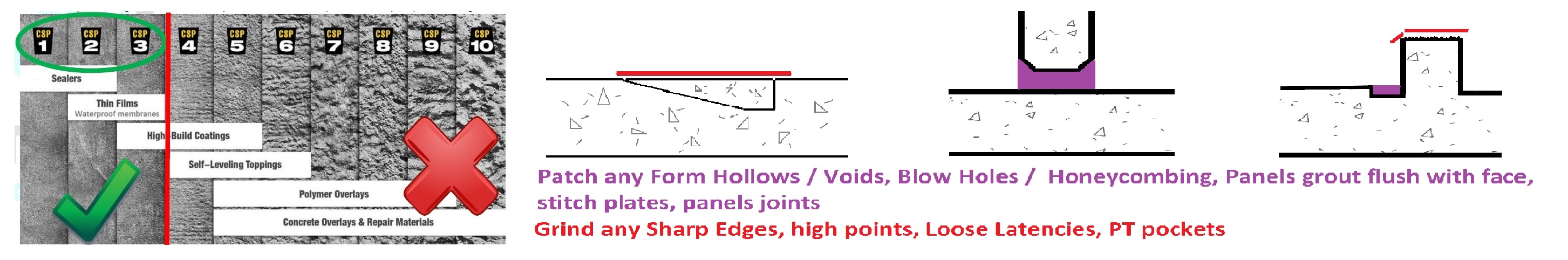
AS 4654.2—2012 states "The substrate shall be smooth, without protrusions, voids or formwork distortions, and clean, dry, and free from dust and contamination."
Finish compatible with membrane, generally not rougher than a wood trowel/float or broom finish concrete, approximately CSP3.
There should be no blow holes / bug holes in the substrate.
Grinding and patching requirements:
To be done by others prior to membrane application. all patching products must be properly cured (3 days) before membrane application.
-
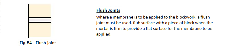
Blockwork:
Mortar in block work needs to be a flush joint, smooth and level with the blocks, no blow outs of mortar.
No Versaloc, or similar block work wall systems for membranes, as there are gaps in the block work which will become a weak point in the membrane.
AS 4654.2—2012 states "The substrate shall be smooth, without protrusions, voids or formwork distortions, and clean, dry, and free from dust and contamination."
-
Lightweight Structures:
Framing supports at a maximum 400mm centres (in one direction). All CFC or plywood sheet edges must also be supported. Do not use tongue and groove plywood. If thicker plywood is to be used support spacing needs to meet AS 1684 for Residential Timber Framed Construction, AS1860 and structural plywood which must comply with AS/NZS 2269.
o Tongue & Groove strip timber floors are not acceptable wet area substrates under
these requirements.
o NOTE: For further information on suitability of materials used for substrates, refer to
the following:
a. Timber, AS 1684 (all parts).
b. Plywood, AS/NZS 2269.
c. Cellulose-cement products, AS/NZS 2908.2 or ISO 8336.
Minimum 19mm treated structural plywood H4 grade or 19mm Compressed Fibre Cement
sheet.
Minimum CD grade with the sanded C face upwards.
Plywood laid with face grain at right angles to supports.
Plywood is to be laid with staggered joints in a brick bond pattern with a 3mm expansion gap
between plywood sheet edges. Bond breaker tape to be applied to all plywood sheet joints
prior to membrane application (Liquid membranes only).
Plywood is screwed with 10g x 50mm SS counter sunk screws at 150mm centres on all sheet
edges and at 200mm centres through the body of the sheet. All screws to be counter sunk 1-
2mm.
Provide 20mm timber fillets at the base of all upstands.
Chamfer all external edges with a minimum radius of 5mm.
Plywood is to be kept dry at all times during construction. Blow/ torch drying the plywood
surface prior to membrane application does not comply. Plywood and framing supports to
be at no more than 5% moisture content.
For Roofs and Roof Decks over living spaces, all cavities must be ventilated and insulated in
compliance with the Building Code of Australia (BCA).
All drains and outlets are membrane compatible.
-
Work area not Clear:
Building Debris, Ponding water, Other trades working in area, and other items found in area preventing membrane works able to be installed. These need to be removed prior to the membrane application.
Removal to be done by others, either the trade responsible or the builder. -
Correction of Hobs required.
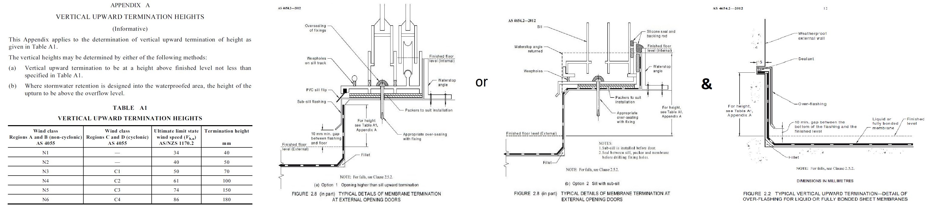
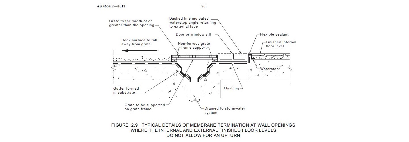
AS 4654.2 – 2012 – 2.8.3 states Door and Window hobs should be as follows:
- “Typical details of external terminations at external opening doors and at wall openings are shown in Figure 2.8 and Figure 2.9.”
- “Openings should be provided with a set-down or hob to provide a vertical surface of sufficient dimension. See also Table A1, Appendix A.” Membrane upturn height must be equal to or greater than the height determined in Table A1, Appendix A. And is determined from the top of the floor finished surface level, which includes membrane termination above pavers on pods.
- “Sub-sill flashing shall be included as part of the membrane system”
Correction of Upturn heights required to allow the membrane to finish above the floor finish surface, including pavers on pods.
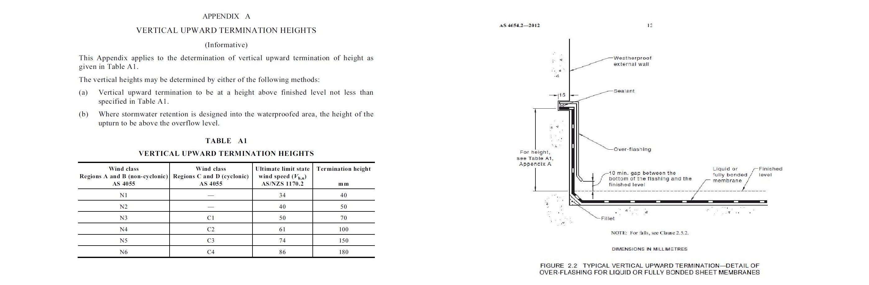
AS 4654.2 – 2012 - 2.8.1.1 Height, states that:
“Where the membrane termination is to prevent water entry, the finished height of the membrane above the finished surface level shall be sufficient to prevent water, including wind driven, flowing over the top of the membrane."
The vertical heights may be determined by either of the following methods:
(a) Vertical upward termination to be at a height above finished level not less than specified in Table A1.
(b) Where stormwater retention is designed into the waterproofed area, the height of the upturn to be above the overflow level. -
Correction of Falls / drainage required.
AS 4654.2 – 2012 – 2.5.2 states:
“Falls in finishes shall ensure water drains to the drainage outlet. Water shall not be retained on the finished surface with the exception of residual water remaining due to surface tension. The fall shall be in the structural substrate, or formed by a screed over the structural substrate. NOTE: Falls for surface drainage should be no flatter than 1 in 100.”
-
Floor wastes / drainage required.
The floor waste must be connected prior to membrane application to allow the water to drain away.
The flange on the floor waste needs to be exposed to allow bonding of the membrane onto the flange, remove all concrete covering flange.
The floor waste must be set down into the slab to comply with AS4564.2 & AS3500 which requires minimum 80mm set down below floor finish for a riser to be inserted. Where a waste is not set down it must be corrected to allow the membrane to turn down as per Figure 2.15 AS4564.2.
AS 4654.2 – 2012 – 2.5.2 states:
“The membrane shall be connected to the stormwater drainage system through a turn down of the membrane into the inlet of the system as shown in Figure 2.15. An alternative connection may have a flange to which the membrane is clamped or attached. -
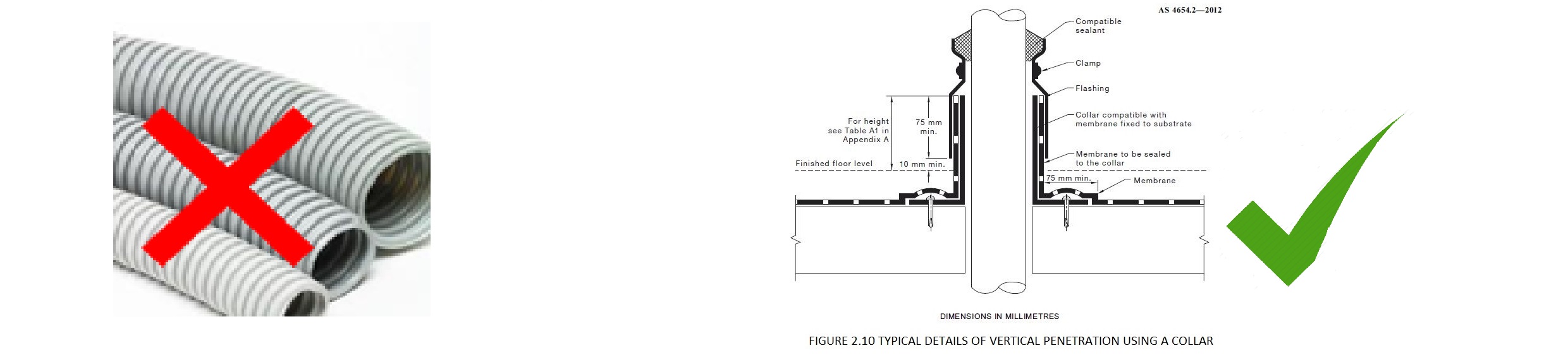
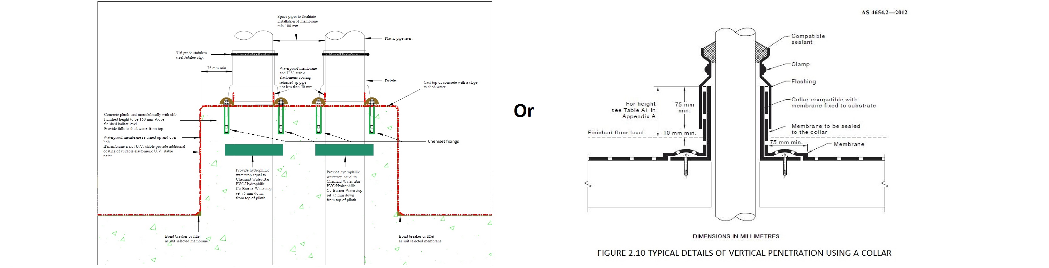
Penetrating the membrane should be avoided at all times where possible, as this is one of the most common causes of water ingression.
AS 4654.2 – 2012 – 2.5.2 states:
“All pipes, ducts and vents should be located within a collar mechanically fixed to the substrate as an extension to the penetration. Alternatively, a collar may be cast into the substrate to form the penetration. A separate collar should be used for each penetration.” & “all penetrations should be packed to stabilize the pipe”
Other contractors should avoid penetrating slabs wherever possible, but where penetrations are essential they must be detailed correctly:
1. Properly secured with flanged sleeves and clamp collars.
a. a separate collar must be used for each penetration, either cast in, or mechanically fixed.
2. Where they occur through a slab, plinths to be poured around them to raise the critical tear point away from potential ponding water
3. Penetration not located next to a floor waste or critical point,
a. ie the floor wall junction
4. Singular (not bunched together) to allow correct detail to occur around each penetration.
5. No flexible corrugated conduit – it always breaks.
6. Use hydrophilic wraps and seals when casting into the slab.
7. No Voids around penetrations. All properly patched.
8. No HDPE pipes installed where the membrane will connect onto the HDPE.
a. If HDPE is required it must be sleeved with a collar that allows bonding of the membrane to occur. -
Flexible conduits must be avoided anywhere you expect to get water. They are made from thinner gauge materials, cannot be properly secured which results in breaking from movement, and usually also break the waterproofing detail. Penetrating the membrane should be avoided at all times where possible, as this is one of the most common causes of water ingression.
AS 4654.2 – 2012 – 2.5.2 states:
“All pipes, ducts and vents should be located within a collar mechanically fixed to the substrate as an extension to the penetration. Alternatively, a collar may be cast into the substrate to form the penetration. A separate collar should be used for each penetration.” & “all penetrations should be packed to stabilize the pipe”
-
Bunched pipes are impossible to detail correctly and not compliant with AS4564.2. The preferred Penetration detail:
- All Pipe penetrations have a plinth installed around them.
- Pipes are individually spaced out and not bunched together.
AS 4654.2 – 2012 – 2.5.2 states:
“All pipes, ducts and vents should be located within a collar mechanically fixed to the substrate as an extension to the penetration. Alternatively, a collar may be cast into the substrate to form the penetration. A separate collar should be used for each penetration.” & “all penetrations should be packed to stabilize the pipe” -
Penetrating the membrane should be avoided at all times where possible, as this is one of the most common causes of water ingression.
Other contractors should avoid penetrating slabs wherever possible, but where penetrations are essential they must be detailed correctly by 2 part epoxy injection to set them in place.
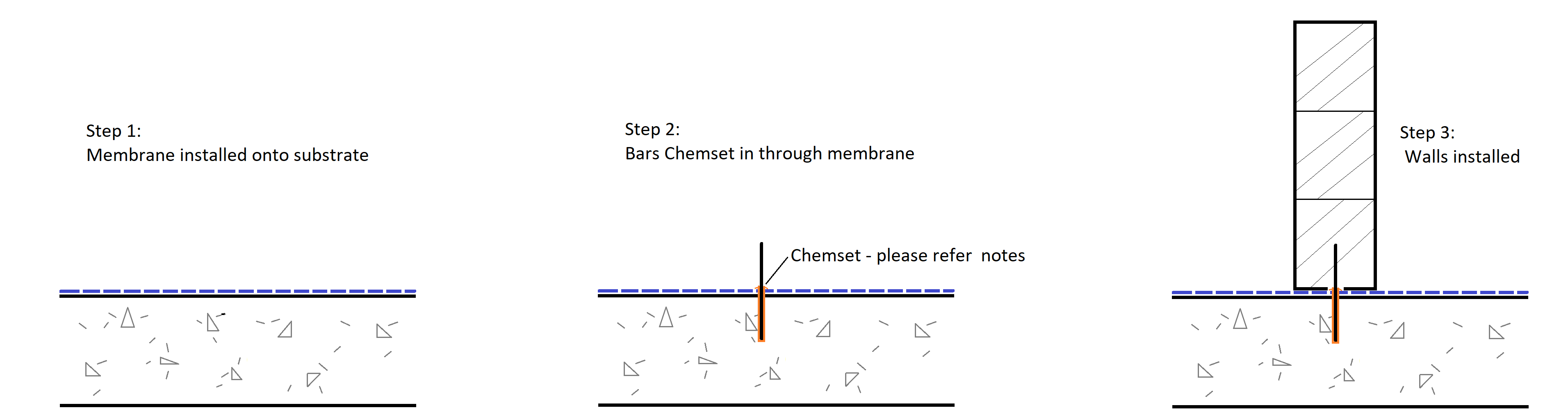
AS 4654.2 – 2012 states that any fixings, threaded rods, starter bars, and bolts should be 2 part epoxy injection set in place to reduce water ingression:
“All penetrations into concrete should be treated with epoxy. All fixings into concrete should be of a chemically injected type in order to maintain the integrity of the waterproofing and substrate.”
Process for 2 part epoxy injection fixings:
1. Overfill holes with 2 part epoxy injection.
2. Blow out dust to make sure adequate bond occurs.
3. Turn Bars clockwise with the thread to avoid any air bubbles occurring in the mix and bonds onto the entire thread.
4. Make sure mix overflows out of the hole.
5. Smooth out 2 part epoxy injection around bars
-
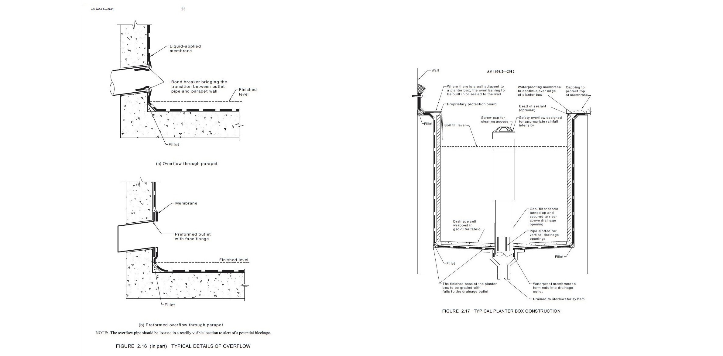
Overflows need to be correctly installed prior to the membrane application.
AS 4654.2 – 2012 – 2.11 states:
“The membrane shall be turned into the overflow, to prevent moisture from tracking behind the membrane. The finished floor level shall not reduce the design flow of an outlet. NOTES: 1 Typical examples of membranes turned into the overflow are shown in Figure 2.16."
All Overflows through walls should be cored on a downward angle away from the area.
Must have preformed outlets installed prior to membrane application. -
Dividing walls - Must allow sequencing to occur for all walls being installed over a membrane:
- Membrane installed onto substrate.
- Bars installed and properly 2 part Epoxy / Chemset, please see notes on Chemset.
- Walls then installed
- If block walls being installed, then:
- Flush mortar joints for section to receive membrane.
- Tops of walls must be steel trowel to smooth core fill
- No voids, blowholes, bug holes, form-work distortions -
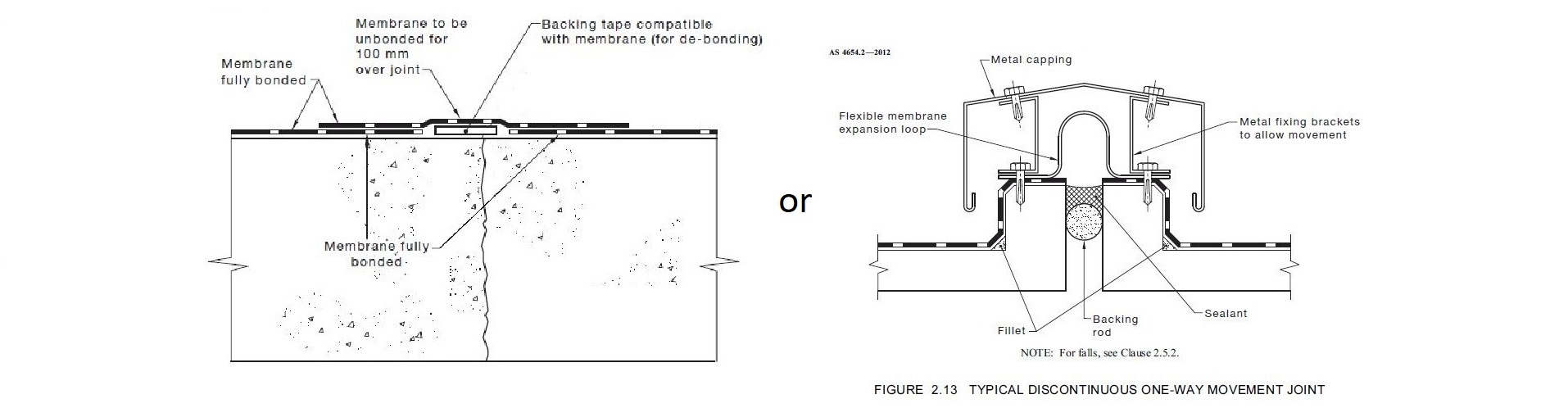
Movement joints and Construction joints should be avoided in high risk locations where water may be constantly present, i.e. through planter boxes etc.
i. Identify where these will occur and quantum of movement is nominated, co-ordinate to reduce risks of failure in the design phase.
AS 4654.2 – 2012 states
“Where a building or structure has construction joints, movement joints or control joints, the membrane shall be either discontinuous or continuous over the joint, to allow for the anticipated movement. Where continuous, the membrane shall be unbonded for the first 100 mm. NOTES: Typical detail of a discontinuous membrane over the joint is shown in Figure 2.13."
2. Typical detail of a continuous membrane over the joint is shown in Figure 2.14. “ -
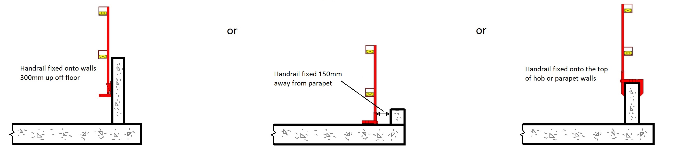
Safety handrails need to be correctly installed above the height of the membrane. Either up on top of the hob or onto the face of the wall / parapet.
It is critical the handrail is not placed onto the floor wall junction, the most critical point, as this will create a weak point in the membrane detail. There must be a 200mm space between the upturn junction and the handrail fixing to allow for a continuous bead of caulk and membrane detail.
Where completion of area is required:
Handrails to be removed and fixing holes to be patched prior, so membrane can be completed in area.
-
Contaminants cause issues with membrane adhesion to the substrate. All contamination such as oils, rubber from tyre treads etc must be removed prior to application of any membrane. Any installed products must be checked for adhesion compatibility prior to ensure the membrane can be warranted with each item.
-
Where a membrane is to be installed over a screed, the screed needs to achieve a compressive strength of 20 Mpa and tensile strength of 1.5 Mpa to be considered acceptable as required under the Australian Standards AS1884 – 2012 & AS3958.1. Please provide evidence that this has been achieved.
-
All caulking by other trades must be compatible with the membrane being installed.
If a polyurethane, Polyurea, Acrylic, and Cementitious membrane is being installed, the caulking product must be a neutral cure polyurethane caulk.
If a Bituminous sheet or Liquid membrane is being installed a Bituminous impregnated caulk must be used.
NO Silicon caulking is compatible with membranes. It is a cause of debonding and delamination issues. -
An Acrylic Fire caulk has been noted in this area. Please note most Fire caulking is not compatible with membranes and is not suitable for external use. This is because Acrylic fire caulks have a propensity to shrink and distort over time, also emulsify when wet.
All caulking by other trades must be compatible with the membrane being installed.
If a polyurethane, Polyurea, Acrylic, and Cementitious membrane is being installed, the caulking product must be a neutral cure polyurethane caulk.
If a Bituminous sheet or Liquid membrane is being installed a Bituminous impregnated caulk must be used. -
AS 4654.2 – 2012 states that “Where a membrane is to be overlayed with another system (e.g. ballast, insulation, soil and the like), the overlaying system shall be compatible with, and not cause damage to, the membrane. & a slip sheet or protection board may be required and not cause damage to, the membrane. & a slip sheet or protection board may be required between the membrane and the overlaying surface "
-
Do not locate the penetrating element hard to the floor and wall junction. This is an impossible detail to make 100% watertight, as there is always a section that cannot be detailed properly, refer picture on right. Make sure there is a minimum of 50-100mm space between the penetration and the wall or floor to allow for proper detailing of the membrane.
-
Post Tension Pockets, Grout Tubes etc:
Substrate surface patching / preparation required prior to membrane application. To be done by others.
AS 4654.2—2012 states "The substrate shall be smooth, without protrusions, voids or formwork distortions, and clean, dry, and free from dust and contamination."
Finish compatible with membrane, generally not rougher than a wood trowel/float or broom finish concrete, approximately CSP3.
There should be no blow holes / bug holes in the substrate.
Grinding and patching requirements:
To be done by others prior to membrane application. all patching products must be properly cured (3 days) before membrane application.
Grout Tubes:
AS3600 state grout tubes should be filled as soon as practicable after stressing, with grouting to occur no less than 4 weeks after stressing.
-
Drop Zone / Exclusion zone in Work area:
Other trades working in area above preventing membrane works able to be installed. Site Foreman to co-ordinate this area to be free from other trades to allow membrane works to be completed. -
Weather – Rain and temperature:
Where weather conditions are not compliant with Supplier T.D.S. requirement for installation of membranes. The following conditions prohibit membrane application to occur:
a) Ambient temperature - between 5°C and 35°C.
b) Do not apply materials during conditions of rain, mist, fog or snow.
c) Ensure rain is not forecast during the application process or less than 4 hours following. -
Comments:
-
Other Finishes already installed:
Other finishes cause issues with membrane adhesion to the substrate and cannot be guaranteed. All installed finishes such as paints, renders, tiles etc must be removed prior to application of any membrane. Any installed products must be checked for adhesion compatibility prior to ensure the membrane can be warranted with each item. -
Damage done to Membrane:
Damage has occurred to membrane after installation. All damages must be repaired as per the suppliers recommendations. -
Existing membranes already installed:
Other finishes cause issues with membrane adhesion to the substrate and cannot be guaranteed. All installed finishes such as paints, renders, tiles etc must be removed prior to application of any membrane. Any installed products must be checked for adhesion compatibility prior to ensure the membrane can be warranted with each item. -
Bubbling and Pinholes in membranes can be a sign of contaminant / moisture issues in the substrate beneath the membrane:
Contaminants cause issues with membrane adhesion to the substrate. All contamination such as oils, rubber from tyre treads etc must be removed prior to application of any membrane. Any installed products must be checked for adhesion compatibility prior to ensure the membrane can be warranted with each item. -
Moisture issues in the substrate beneath the membrane will result in future issues:
AS 4654.2 – 2012 states:
“moisture content in the substrate should be under 8.0% for most membranes (5% or less for Spray applied Polyurea membranes). If a Waterproof membrane is applied to a damp/green substrate there is a high risk the application will either de-bond or become fractured due to the force of the moisture trying to evaporate from the substrate. When there is trapped moisture in the substrate membranes can show signs of blistering or bubbling known in the industry pin holing, and delamination.” -
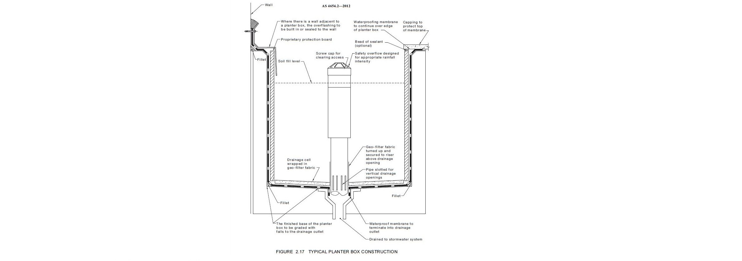
Waste locations and overflow pipes:
• Proper flanged leak control wastes need to be installed into each planter box, appropriately located and suitable number of wastes for each planter box size, amount of water flow from irrigation and rain needs to be considered to determine the number of wastes and diameter of drainage system pipes.
• Overflow should be installed that connect into the waste point and allow access to inspect and clear any blockages.
• AS 4654.2 – 2012 2.13 Planter boxes states and shows that “The planter box should be provided with a suitable overflow” to allow inspections and access to clear blockages.
o The overflow rises should be smaller than the waste, so the riser does not impede water drainage: -
Weep holes or drainage points through walls are not compliant with the AS 4654.2 – 2012 and are often the points of failure and water ingression.
Overflow drainage outlets through walls:
• Must be Positioned on parapets higher than the floor finish level but lower than the top of the hob.
• Proper flanged leak control wastes need to be installed into each planter box, appropriately located and suitable number of wastes for each planter box size, amount of water flow from irrigation and rain needs to be considered to determine the number of wastes and diameter of drainage system pipes.
• Overflow should be installed that connect into the waste point and allow access to inspect and clear any blockages.
• AS 4654.2 – 2012 2.13 Planter boxes states and shows that “The planter box should be provided with a suitable overflow” to allow inspections and access to clear blockages. -
-
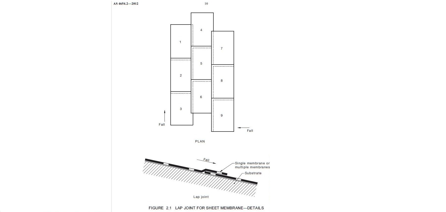
Sheet Laps must be laid compliant with the AS 4654.2 – 2012, where the leading edge is facing down with the direction of falls. Where laps are incorrectly installed against the falls these are often the points of failure and water ingression.
AS4654.2 states The longitudinal direction of placement of the membrane shall commence at the lowest point and be in the same direction as the fall of the supporting substrate as shown in Figure 2.1. -
Screeds and overlaying concrete:
AS 4564.2-2012 states 2.15.1 & 2.15.2 that:
III. Where the topping or bedding mortar is structurally sufficient not to require bonding to the substrate, a double slip sheet shall be laid over the membrane to separate it from the screed. Slip sheets must consist of a minimum of 2 layers of 200 micron polyethylene builders plastic. -
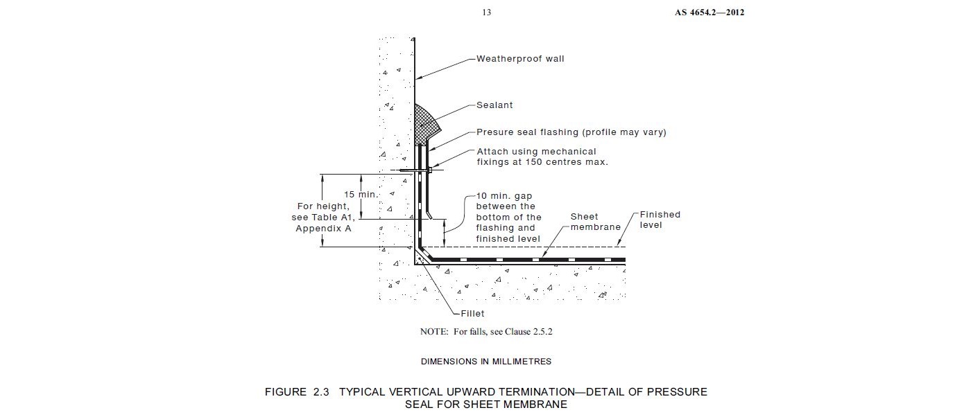
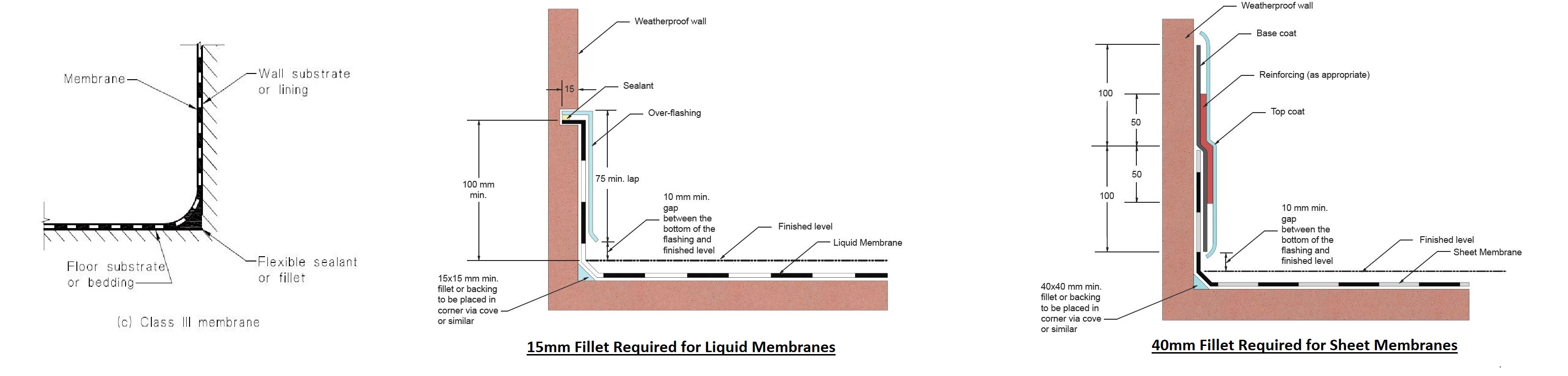
Sheet membrane termination must be compliant with the AS 4654.2 – 2012, where the termination edge is held in place by a pressure flashing or otherwise known as a K-flashing. Where termination edges are not correctly secured these are often the points of failure and water ingression.
AS4654.2 states that the termination of a pressure seal flashing shall comply with the following:
(a) Pressure seal flashing shall be attached using mechanical fixings at maximum 150 mm centres. The lap from the bottom edge of the mechanical fixing to the bottom edge of the pressure seal flashing shall be a minimum of 15 mm.
(b) Sealant shall be used to encapsulate the pressure seal flashing to the weatherproof wall.
(c) There shall be a minimum 10 mm gap between the bottom of the flashing and finished level. -
Calcification or efflorescence caused by water coming from a deck or balcony that occurs
on walls below or beside the deck or balcony, or that appears in the mortar joints of the
deck or balcony tiling, is deemed defective by the VBA and BCA. -
AS 4654.2 – 2012 – 2.8 states:
I. “Where the membrane termination is to prevent water entry, the finished height of the membrane above the finished surface level shall be sufficient to prevent water, including wind driven, flowing over the top of the membrane. NOTE: For information on termination heights, see Appendix A.”
d. Membrane upturn heights are often the most misunderstood component of the standards, as they refer to the top of the finished floor surface which includes tiles, pavers on pods, synthetic turf etc. Figures 2.2, 2.3, & 2.8 show the membrane upturn height as the measure from the top of the tile, paver etc, Table A1 does not include the section of upturn below the tile / paver finish. This upturn above the floor finish must comply with Table A1 in Appendix A.
Minimum membrane heights above floor finishes start at 40mm and get as high as 180mm depending on a variety of environmental conditions. -
Ponding on waterproof decks and balconies:
Waterproof decks and balconies are defective if water ponds (with the exception of residual water remaining due to surface tension) from blocked drains or does not drain to the outer edge overflow or a storm water inlet.
Decks and balconies that are required to be waterproofed are defective if they are not provided with adequate drainage and provision for overflow.
If Wastes are blocked there must be provision for an overflow (please see section 2.11 in AS 4654.2 – 2012).
There must also be a regular inspection process for checking and clearing any blockages, should they occur. Recommend this is done monthly. -
Ponding on waterproof decks and balconies:
Waterproof decks and balconies are defective if water ponds (with the exception of residual water remaining due to surface tension) or does not drain to the outer edge or a storm water inlet.
Decks and balconies that are required to be waterproofed are defective if they are not provided with adequate drainage and provision for overflow.
If there are blockages there must be provision for an overflow (please see section 2.11 in AS 4654.2 – 2012).
There must also be a regular inspection process for checking and clearing any blockages, should they occur. Recommend this is done monthly. -
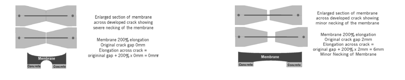
Crack formation in concrete after membrane installation has occurred is indicative of poorly performing concrete, structural stress, structural failure or a structural design issue. The industry and concrete standards AS 3600:2018 recognise a maximum allowable crack width of 0.3mm. Cracks larger than 0.3mm are regarded as problematic and may require repair. The majority of membranes can accommodate structural crack widths (forming after membrane installation) from 0mm to 0.6mm. Accommodating cracking post membrane application is limited for all membranes, even those with very high elongation properties.
• For example; membrane with 600% elongation can be overstressed by a crack forming to 1.0mm width from nothing – 600% of zero mm = zero mm
- Where hairline cracks form after the application of the membrane, the membrane copes by necking or reducing its film thickness over the crack. As the crack gets larger the membrane gets thinner to a stage where it becomes ineffective as a waterproof membrane and eventually shears or tears to break completely across the crack. -
Double Layer slip sheet for Screeds and overlaying concrete:
I. AS 4564.2-2012 states 2.15.1 & 2.15.2 that:
II. Where a membrane is to be overlayed with another system (e.g. tiles, pavers, ballast, insulation, soil and the like), the overlaying system shall be compatible with, and not cause damage to, the membrane. Which means some protection boards should be allowed for by the trade installing the next system.
III. Where the topping or bedding mortar is structurally sufficient not to require bonding to the substrate, a double slip sheet shall be laid over the membrane to separate it from the screed. Slip sheets must consist of a minimum of 2 layers of 200 micron polyethylene builders plastic. -
Disabled access (DDA) requirements where the external balcony floor finish needs to be at the same height as the internal floor finish. AS 4654.2 – 2012 states that “Where circumstances do not permit the inclusion of a set-down or hob (e.g., for wheelchair access), a gutter should be formed into the substrate immediately in front of the opening” see figure 2.9.
-
AS 4654.2—2012 2.7 FILLETS States that:
Fillets shall be used when a membrane changes from a horizontal to vertical or vertical to
vertical plane.
NOTE: The cove should be dimensioned as a 40 mm × 40 mm fillet/cove for ‘sheet’ membranes and a 15 mm × 15 mm fillet/bond breaker for ‘liquid’ membranes. -
AS4654.2 states that the treatment of junctions, lap joints, seams and cold joints shall be according to the type of system, and comply with the following minimum dimensions:
(a) Bituminous sheet membrane Sheet membranes shall be laid with minimum side laps of 70 mm and minimum end laps of 150 mm, both fully bonded with end laps staggered.
(b) Synthetic rubber Factory-vulcanized joints shall be overlapped 40 mm minimum. Field joints that are made with adhesives shall be overlapped a minimum of 50 mm for side laps and a minimum of 100 mm for end laps, with end laps staggered.
(c) Flexible polymer sheet Factory-welded seams shall be overlapped a minimum of 40 mm. Field-welded joints shall have a minimum of 100 mm overlaps when used over insulation boards, and a minimum of 75 mm overlaps in other instances. Joining may be made with a minimum of 100 mm wide overlapping tape, with end laps staggered. -
Moulds can give off toxic chemicals, called mycotoxins, and if there's a lot of mould these nasties can cause allergic reactions, asthma and flu-like symptoms.
Mould associated with damp buildings can trigger nasal congestion, sneezing, cough, wheeze, respiratory infections and worsen asthma and allergic conditions.
People who are more susceptible to these symptoms and other serious health effects include those with:
• weakened immune systems
• allergies
• severe asthma
• chronic, obstructive, or allergic lung diseases.
You should seek medical advice if you are concerned about the effects of mould.
Mould only grows when there is sufficient moisture on a surface or humidity in the air. Common causes include:
• leaky roofs and walls including and blocked gutters and downpipes
• leaky plumbing
• condensation from cooking, showering, clothes drying and from breathing in areas with poor air circulation eg cupboards and corners and furniture against uninsulated outside walls. Avoid conditions encouraging mould growth, by using heat, insulation and ventilation. -
Penetrating the membrane should be avoided at all times where possible, as this is one of the most common causes of water ingression.
AS 4654.2 – 2012 – 2.5.2 states:
“All pipes, ducts and vents should be located within a collar mechanically fixed to the substrate as an extension to the penetration. Alternatively, a collar may be cast into the substrate to form the penetration. A separate collar should be used for each penetration.” & “all penetrations should be packed to stabilize the pipe”
Other contractors should avoid penetrating slabs wherever possible, but where penetrations are essential they must be detailed correctly:
1. Properly secured with flanged sleeves and clamp collars.
a. a separate collar must be used for each penetration, either cast in, or mechanically fixed.
2. Where they occur through a slab, plinths to be poured around them to raise the critical tear point away from potential ponding water
3. Penetration not located next to a floor waste or critical point,
a. ie the floor wall junction
4. Singular (not bunched together) to allow correct detail to occur around each penetration.
5. No flexible corrugated conduit – it always breaks.
6. Use hydrophilic wraps and seals when casting into the slab.
7. No Voids around penetrations. All properly patched. -
Small holes and bubbles in the membrane are often a sign of off gassing.<br>Whenever liquid applied coatings are used over cementitious or other porous substrates, the possibility of blisters and/or pinholes exists. This phenomenon is caused by the expansion of moisture vapor and air that is trapped in the substrate (out-gassing).<br>Blisters resulting from out-gassing can be cosmetic in nature and do not usually compromise the waterproofing integrity of the applied membrane system. The preferred option is usually that the installed waterproofing system is not disturbed. Where blisters are to be repaired, care must be taken to a soundly bonded margin and a homogeneous structure is formed between the repaired area and the surrounding installed waterproofing<br>
-
There is a need to be familiar with the chemical compatibility of all the materials that will be in contact across the building envelope. Issues can result from either:<br>i. Incompatibility that results in the chemical breakdown of the less “noble” material which is a similar failure mode to the reaction when dissimilar metals are in contact with each other.<br>ii. Incompatibility that causes no physical change in either of the materials, but instead is characterized by the inability of the two materials to remain bonded for the service life of the system. For example, the materials can be in contact with no adverse effects to their physical properties, but they become de-bonded over the course of their service life.<br>Common items that have bonding compatibility issues with waterproof membranes are:<br>• Silicon caulking – often used by services trades<br>• Aluminium – due to the silicon's used to extrude it during manufacturing.<br>• Steel - due to latent oils and the oxidisation that occur on the surface in the extrusion process. Along with the smoothness of the surface profile.<br>• HDPE plastics – often used in pipes. It is a form of recycled plastic that can only be bonded to by itself through heat friction welding. <br>
-
General Comments or Summary:


-
all Waterproofing to be installed as per:
- AS/NZ 4858 Wet Area Membranes Materials
- AS3740 Waterproofing of Wet Areas Design and Installations
- AS 4654.1 Waterproofing Membrane systems for exterior use Above Ground Only Part 1 Materials
- AS 4654.2 Waterproofing Membrane systems for exterior use Above Ground Only Part 2 Design and Installation
- AS 3958.1 Tiling
- Building Code of Australia requirements.
Finish
-
Auditor Name and Signature:
-
Company Name Here .....
Phone: 1300 .................
Address: ..............................
ABN here 123456789