 V9.1")


Information
-
FDH Name
-
Conducted on
-
Location
-
Prepared by
-
Personnel present if applicable.
Health and Safety
-
All Health and Safety as per UFF and contractors policy, OSH guidelines
-
Have you signed onto site.
-
Take a photo of the Sign On sheet (ensure the correct focus)
-
Have you sighted the Contractors JSA.
-
Additional notes and comments
General
-
Site left clean and clear from all task waste
-
Reinstatement matches surrounds, is at correct level and contour, and shows no substance.
-
No visual damage to the closest premises (fences, etc)
-
Record all damage.
-
Additional notes and comments
Plinth Installation
-
Inside of plinth free of all waste
-
Damage to the plinth (including hairline fractures)
-
Plinth placement correct to build pack. ( Correct address and position)
-
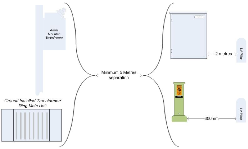
FDH proximity to power utilities.
-
-
Plinth installed level.
-
Take a photo of the spirit level as an indication of the plinth angle.
-
Plinth installed to correct ground level (no trip danger)<br>
-
Plinth concrete surround installed as per guide
-
Correct seal between the FDH and the plinth.
-
Correct bolts and washers used to secure FDH base to plinth
-
Additional notes and comments
Duct and Cable Management.
-
-
ABF Ducts inside the plinth are installed in order as per FDH installation guide V9.2
-
ABF Feeder duct in correct position
-
100mm ADSS duct sealed with an end cap.
-
Uniform cement layer of 3 - 5 mm seal 150 - 200mm from the base of the plinth
-
Distribution Multi-duct installed through gland plates with correct micro - duct sequence
-
All micro duct including the 14/10mm is trimmed to 50mm.
-
Gland Plates secured to FDH and gaps sealed where required
-
Duct tracer wires terminated to the underside of gland plates as per guide
-
All micro ducts sealed.
-
Take a photo of plinth internals, duct and duct labels.
-
Additional notes and comments

Functional Earth
-
Earth bar installed as per guide
-
Functional earth secure into the base of the plinth
-
Earth wire terminated to earth bar with brass plate
-
Earth wire terminated to gland plate ( no exposed conductors)
-
Additional notes and comments
Provisioning from FDH (ABF)
-
Has the splice trays got the associated duct label on the edge of the tray.
-
Has the splice tray and DPP been pre-allocated.
-
Does the pre-allocation conform to UFF-3-002 Installation of UFF FDH cabinets.
-
Any non-conforming issues.
Labelling
-
Take a photo of the cabinet certificate located on the cabinet door
-
Multi ducts labeled as per guide
-
Gland plates labelled.
-
Cabinet external door labelled.
-
Cabinet internal door labelled.
-
Feeder Cable Labelled. i.e. HMW102[0004Y]
-
ADSS Cables Labelled i.e. HW54673_A3[54673]
-
Splice tray labelled<br>Feeder: HMW102 F1-12 OCP 1-12<br>ADSS: HW54673_A1 F1-12 FAT40001 F1-12 DPP 1-12<br>ABF Dist: HW54673_01_04 DPP 13-24
-
Has the Pigtails been labelled 100mm from the connector end
-
FDH Records book laid out correctly and data entered.
-
Take a photo of all tray labels.
-
Take a photo of each page of the records book.
-
Additional notes and comments
ADSS Cables and Splice Trays
-
Is there ADSS
-
ADSS Cable gland plate grommet tightened around cable
-
Spare gland plate positions sealed
-
ADSS Cable strength member secured (does not slid freely)
-
ADSS tubes coiled neatly in storage bins. The spare/EOI must be placed in the top tray.
-
Spare tubes in storage bins are completely within the bin
-
Tube transitions correctly from storage bin to splice trays
-
All working tubes over sleeved
-
Tubes secure into splice tray
-
Splice tray installed correctly
-
Splices labeled in tray (both Feeder and any provisioning (BAYP)).
-
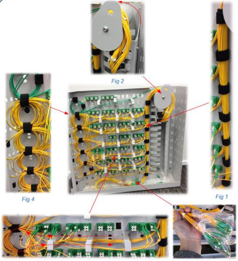
Pigtails manage correctly to patch panel and secured as per guide
-
Additional notes and comments
Feeder Cables and Splice Trays
-
Inside main compartment free of waste.
-
Feeder duct has gas block connector installed correctly and tightened around cable
-
Feeder cable gland plate grommet tightened around cable
-
Cable sheath removed to appropriate location and secured to the backframe.
-
Tubes over sleeved and taped at cable.
-
Spare tubes managed to trays as per guide and secured.
-
Feeder Cable strength member secured (does not slid freely).
-
Allocated tubes managed to trays as per guide and secured.
-
Feeder Pigtails installed correctly to patch panel as per guide
-
Take a photo of the splice trays and feeder cable
-
Additional notes and comments
Patch Panel
-
Pigtail management bars installed at front and back of panel.
-
Pigtails managed correctly at back of panel.
-
Patch panel rear cover installed.
-
All dust caps installed at front of patch panel.
-
Splitter output legs
-
Splitters present and distribution fibres managed as per installation guide .
-
Splitters installed and connected to feeder fibre on patch panel.
-
Splitters output legs managed correctly.
-
Take photos of the front and rear of the DPP
-
Additional notes and comments
Moisture
-
Roof membrane installed within the FDH.
-
Installation of the micro duct gland membrane (bag to go over the sponge) no holes present in the unpopulated duct gland
-
Gaps between the micro duct gland plate sealed with a bead of silicon sealant or foam strip.
-
Evidence of moisture ingress in the plinth area.
-
Evidence of moisture ingress in the main optical compartment.
-
take photos if there's any obvious causes and report this to the Standards Department.
-
Take photo of the underside of the gland plates
-
Additional notes and comments
Sign Off
-
On site representative
-
Auditor's signature


