")


Title Page
-
Inspected by
-
Inspection date
Observations
-
Has there been any reports of any air leaks?
-
Have you Identified the area of leak before isolating the power and/or air?
- Yes
- No
- N/A
Safety
-
Electricity - Have you Isolated the Power? (LOTO)
-
Have you discharged any stored/potential electrical energy?
-
Compressed Air - Have you isolated the compressed Air?
-
Have you discharged any stored/potential air? (LOTO)
-
Have you filled out as LOTO check sheet?
-
Is there sufficient lighting in the area?
Preparation
-
Confirm The Serial Number Of The Machine S/N: C109350?
-
Do you have all the relative tools, consumables and checking equipment to perform the service?
-
Are you wearing all the required PPE?
-
Do you have a safe working area?
Running Maintenance
-
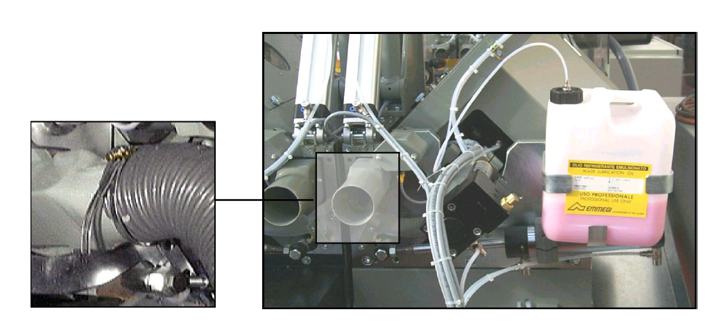
The machine is provided with suction intakes diameter 70 mm on the rear side of each cutting head serving
for connection of the silenced swarf exhauster MG4 through relative suction hose. Secure the hose on the
intakes of the cutting-off machine and swarf exhauster with hose clamp.
The swarf exhauster is provided with its own on/off switch and plug. Provide a main switch (thermal magnetic
circuit breaker) of rating suitable for the total installed power and supply voltage.
If automatic switching on of the swarf exhauster is required during the work cycle, connect it to socket at the
side of the control panel (optional).
Ensure the extraction pipes are fully secured and are in good working order, with no leaks splits or holes in the pipe. -
Are the extraction pipes secured and in good working order?
-
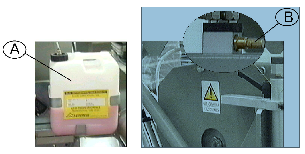
To top up the coolant tank with emulsified oil, unscrew plug (A) of the tank and be careful when filling that no
dirt can enter which could impair the oil flow.
Handling of the coolant is subject to regulations for PROFESSIONAL USE.
The amount of coolant can be adjusted by means of screw (B): turn clockwise to decrease coolant, anticlockwise
to increase it. Coolant flow can be shut-off by turning the screw fully: just the compressed air flow
remains.
ATTENTION
The tank should never remain without oil in order to avoid risk of damaging the pump. -
Are the fluid Lubrication levels at the correct level?
-
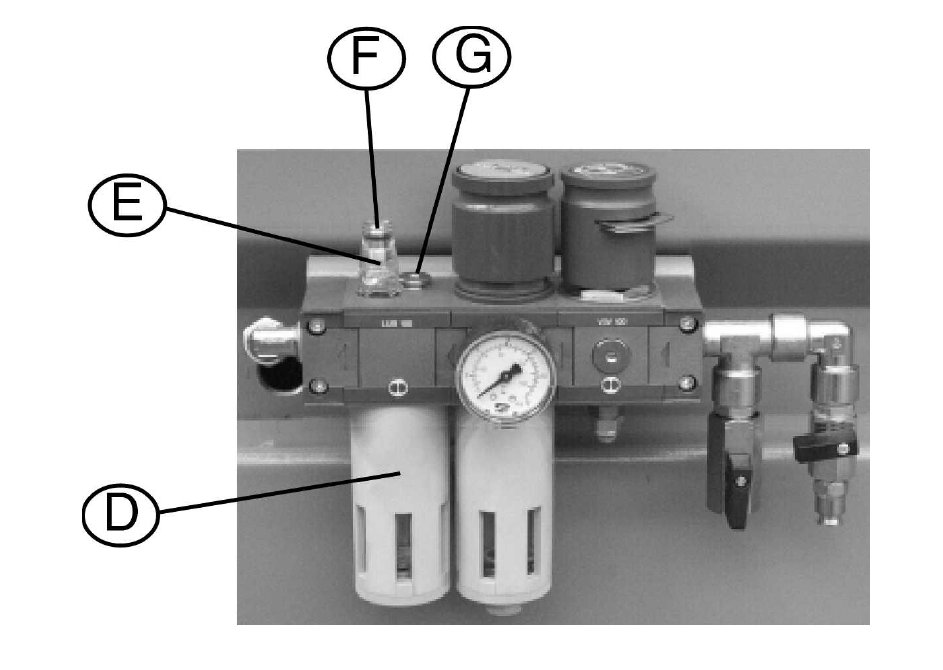
Topping up the oil in the compressed air preparation unit
Before proceeding to top up the oil in the compressed air preparation unit, shut-off air from the supply line.
One of two different methods can be used, namely:
- unscrew reservoir (D) with a pin spanner, dia. 3 mm, and fill it to 3/4
- unscrew plug (G) and top up level until 3/4.
Next check the oil flow via sight (E): it should be one drop every 3/5 cuts. To adjust the oil flow, turn screw
(F), clockwise to decrease the flow, or anti-clockwise to increase it. -
Is the Oil level the correct level?
-
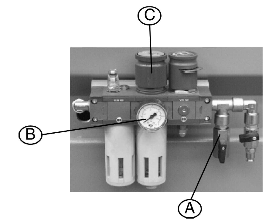
Checking the Pneumatic Pressure levels
The machine operates at a pressure of 6 bar. If the pressure is insufficient, adjust the pressure switch after
switching off current to the controls.
Check the exact level of the pressure on pressure gauge B. If pressure requires adjustment, raise knob C,
and turn clockwise to increase the pressure or vice versa to decrease it. -
Are the Pneumatic Pressure Levels Correct
-
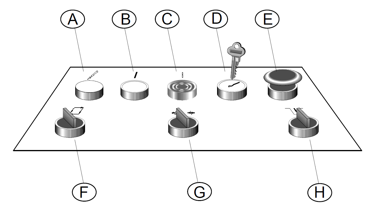
Checking the Graphic Symbols and Control Functions
A - Power on indicator lamp: lights up when the machine is switched onCycle START switch: when actuated
together with the user attendance switch, it allows the cutting cycle to start
B - Illuminated main start push button: determines general operating status of the machine; switches off if an
automatic alarm is given or the emergency push button is pressed; when pressed, it allows the machine to
resume operation
C - Limit stop disable push button: used after disabling the overtravel alarm
D - Overtravel alarm disable: when key is turned to right and the alarm reset push button pressed, the
overtravel alarm is disabled
E - Emergency push button: when this push button is pressed, the machine is fully stopped and placed in
emergency condition
F - Cycle START switch: when actuated together with the user attendance switch, it allows the cutting cycle to
start
G - Clamp open/close selector switch: when turned to right, the clamps are closed, vice-versa, clamps are
opened
H - User attendance switch: when actuated it informs the machine that the operator is present -
Are the Graphic Symbols & Control Functions Clear and easy to read?
-
Do all Control functions operate as they should?
-
Cutting Length & Clamp Preventive Checks
1. Turn the main switch to position “1”
2. Check that the power on indicator lamp A lights up
3. Check compressed air pressure1
4. Check coolant level
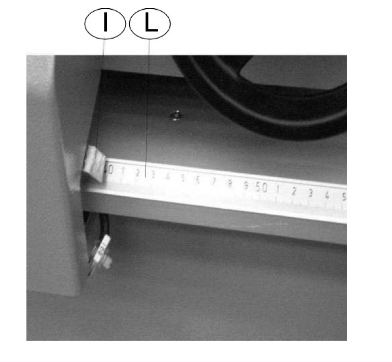
5. Proceed to reset the machine and check that the cutting length showed by the computer corresponds to
the actual position of the moving cutting head given by index I on metric scale L
6. Check the clamps: close the ON/OFF valves of the vertical clamps and actuate selector switch G: the
horizontal clamps are closed. -
Does the cutting length indicator correspond with the Computer?
-
Do the Vertical clamps operate as they should?
-
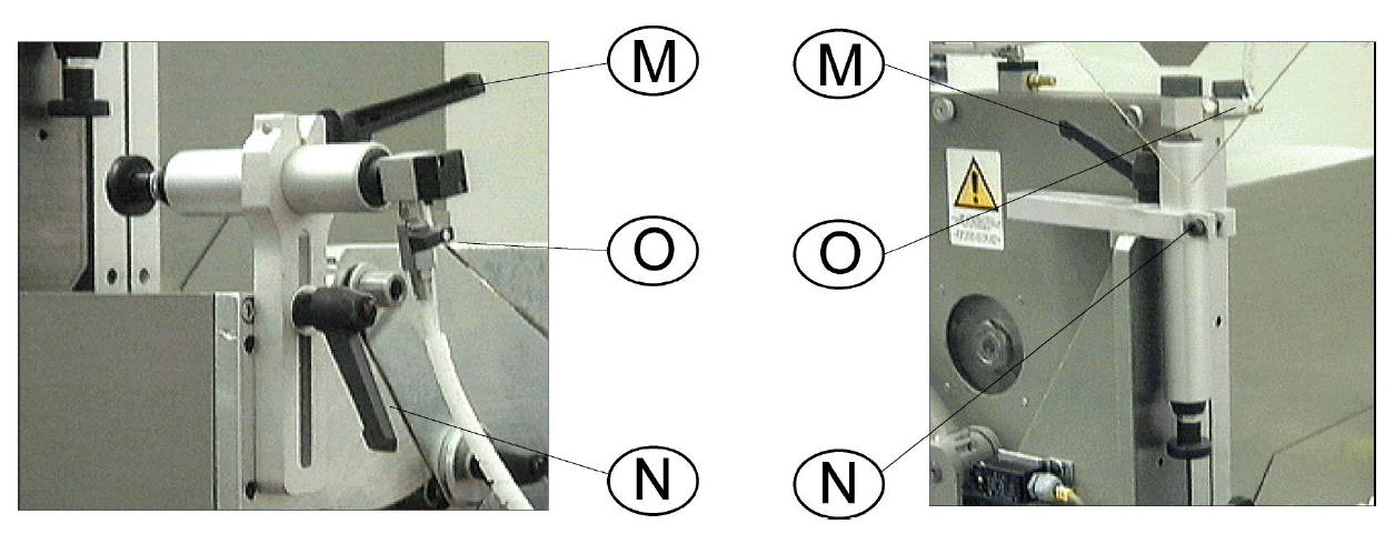
Clamp Adjustments For accurate cutting of the profile, it is necessary that the clamps firmly grip the workpiece during cutting. If
necessary, proceed to correct the position of the clamps through the following adjustment members:
M - locking lever for longitudinal adjustment of the clamp;
N - locking lever for vertical adjustment of the clamp;
O - clamp pressure ON/OFF valve.
For efficient profile clamping, adjust the clamps to give a clearance of approx. 10 mm from the profile. -
Are the clamps correctly adjusted?<br>
-
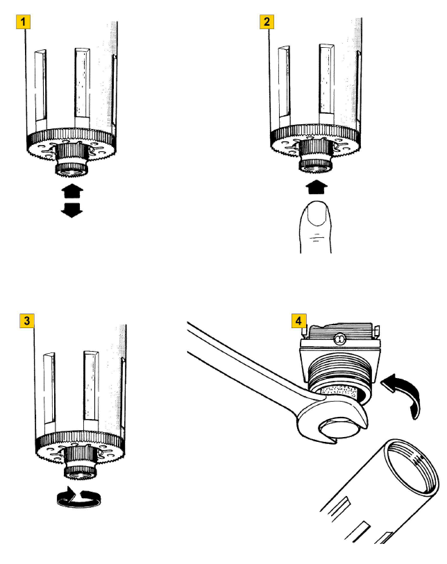
TO DRAIN THE CONDENSATE
The condensate drain valve can be used in manual or automatic mode:
1 During rest condition, the valve is semi-automatic. This position allows draining of condensate when
pressure is missing; when pressure returns, the valve is closed automatically.
2 However, if necessary, the condensate can also be drained in the presence of pressure. To do so, press
the button on the valve up.
3 Lastly, when the button is turned to the right, the valve is locked; in this position, there is no drainage.
4 When it is necessary to clean, merely unscrew the bowl, then the guard of the cartridge unit. Now proceed
to clean or replace the cartridge. -
Have you drained and inspected the condensate
-
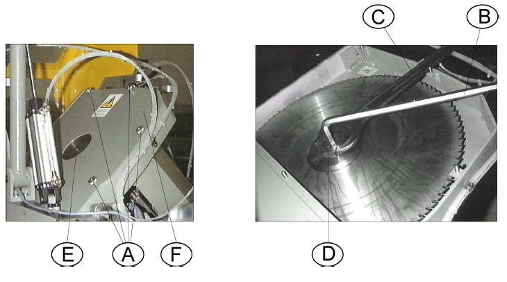
TO REPLACE TOOLS
MAKE SURE THAT THE BLADE TO BE REPLACED IS STATIONARY!
Such operation must be performed with the heads at 45° and the machine switched off (main switch turned to
"0"):
• unscrew knurled nuts (A) by hand and remove cover (F);
• holding the blade spindle still with hexagonal spanner (B), turn nut (D) with spanner (C) in the direction of
blade rotation.
• when remounting the blade, carefully clean the spindle, mounting flange and front flange;
• before starting the machine, make sure that the blade is securely fastened and guard with cover (F) is
closed.
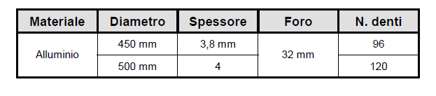
4.5.1 TOOL TABLE
When cutting solid material, the blade characteristics depend on the section to be cut. Hence it is always
necessary to contact the manufacturer.
The following table shows standard blade types for light alloys:
Materiale Diametro Spessore Foro N. denti
450 mm 3,8 mm 96
Alluminio
500 mm 4
32 mm
120 -
INFORMATION - TOOL TABLE
When cutting solid material, the blade characteristics depend on the section to be cut. Hence it is always
necessary to contact the manufacturer.
The following table shows standard blade types for light alloys: -
Have the grease points been fully lubricated?
General House Keeping
-
Has the area around the machine been fully cleaned?
-
Are the cleaning shadow boards populated?
Spares & Consumables
-
If spares & Consumables have been used, have you emailed stores with a complete list for replenishment?
Finalisation
Comments
-
Anything else to report?
-
Note