


Title Page
-
Inspected by
-
Inspection date
Observations
-
Has there been any reports of any air leaks?
-
Have you Identified the area of leak before isolating the power and/or air?
- Yes
- No
- N/A
Safety
-
Electricity - Have you Isolated the Power? (LOTO)
-
Have you discharged any stored/potential electrical energy?
-
Compressed Air - Have you isolated the compressed Air?
-
Have you discharged any stored/potential air? (LOTO)
-
Have you filled out as LOTO check sheet?
-
Is there sufficient lighting in the area?
Preparation
-
Confirm The Serial Number Of The Machine S/N: C118271
-
Do you have all the relative tools, consumables and checking equipment to perform the service?
-
Are you wearing all the required PPE?
-
Do you have a safe working area?
Running Maintenance
-
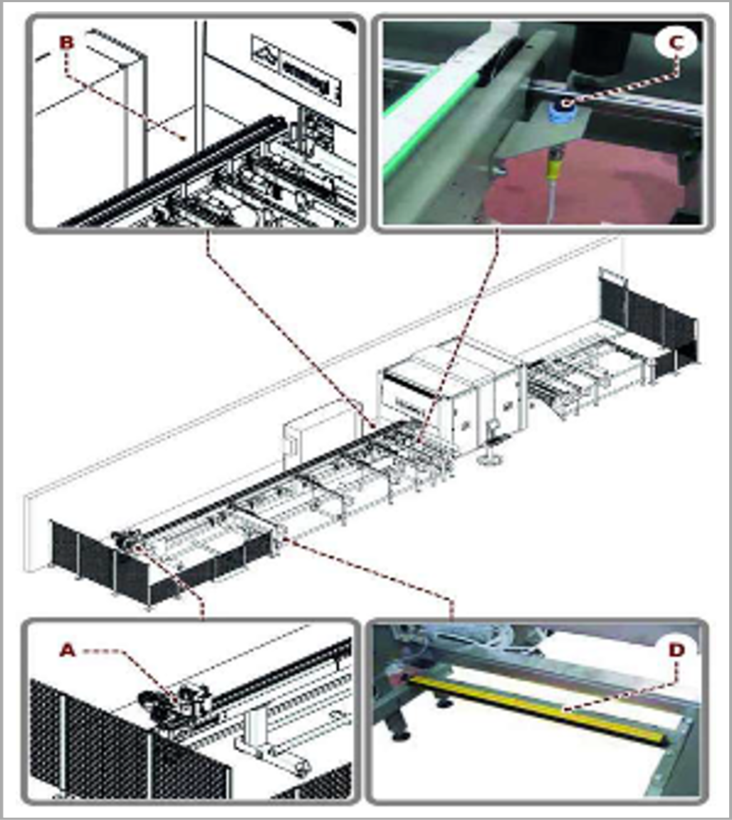
To keep the machine fully efficient, all its components must be cleaned frequently.
In particular clean :
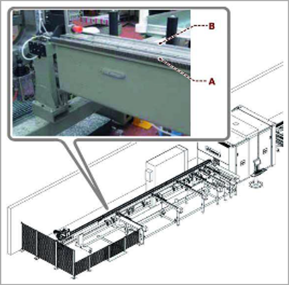
Clean the pusher arm (A).
Clean the part of the loader (B) near the cabin.
Clean the feeder rollers. Clean all the catenaries.
Clean the feeder photocell (C) and those of the unloader.
Clean the light curtains (D) at the base of the feeder frame. -
Have you cleaned sections A, B, C & D?
-
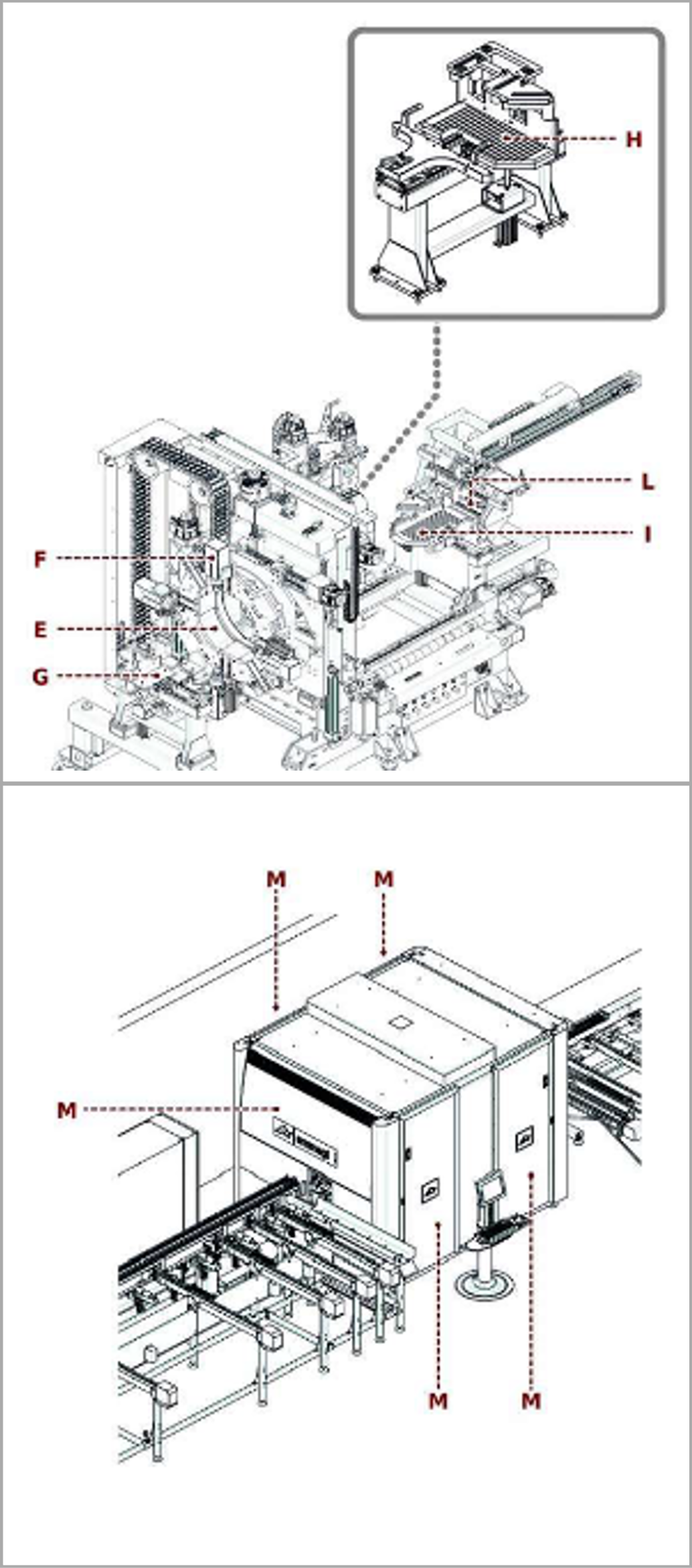
Enter the cabin and thoroughly clean the inside, remove all swarf using a suitable industrial vacuum cleaner.
Use a brush to clean the slewing ring (E). Clean the electrospindles (F) and make sure the ventilation ducts are free.
Clean the surfaces and terminals of clamps (G), (H) and (I).
Clean the rollers (L) of the puller. Clean all the catenaries.
Clean all the guides, cams and microswitches.
Empty the swarf collection trays and clean the surrounding area.
Clean the swarf evacuation belt (optional) and the surrounding area.
Apart from systematic cleaning, perform the following operations whenever necessary.
Clean the glass of the cabin (M), the control panels and the monitor with a soft, moist cloth or sponge and a suitable detergent or a standard glass cleanser. -
Hove you cleaned out sections E, F, G, H, I, L & M?
-
Clean the control indicators (including the monitor and the computer keyboard) , the indicator lights, the rating plates and in particular the safety signs whenever necessary.
All data plates and decals on the machine or on parts of the machine must be clearly legible.
If data plates and decals have deteriorated order replacements from the EMMEGI spare parts service -
Control Indicators And Input Devices cleaned?
-
Data Plates readable and clearly legible?
-
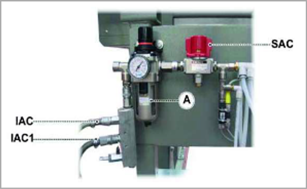
Depressurise the machine by opening valve
(SAC) .
Disconnect the air inlet pipe from the quick coupler (IAC) (IACl).
To perform any cleaning, just unscrew the cup
(A) and clean or replace the cartridge.
Do not use trichloroethylene based detergents (such as benzol, acetone, and other liquids containing softening agents) . -
Have you cleaned the filter unit bowl as above?
-
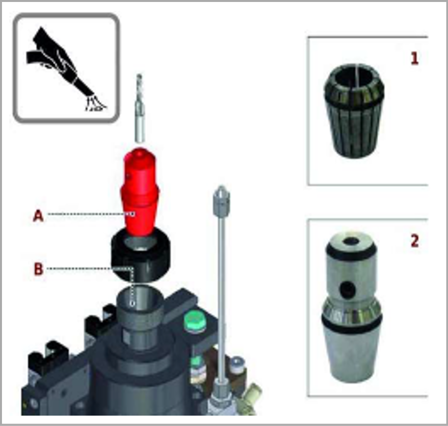
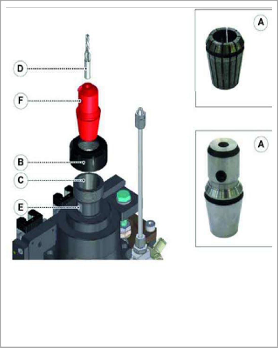
Vacuum the tool holders and the seat, clean with a cloth with ethyl alcohol.
Check the cleanliness of the conical surfaces of the tool holder taper (A) and of its seat (B) .
If cleaning is necessary, use suitable commercial detergents (trichloroethylene, alcohol , etc.) ensuring that no damage is caused to the surfaces.
1) Collet ER32
2) Weldon tool holder. -
Have you cleaned the Electro Spindle & Tool Holder as above?
-
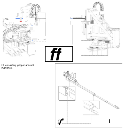
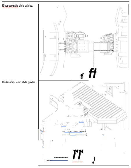
Check the rack (A) at the back of the machine to see if it is dirty and, if necessary, clean it thoroughly removing swarf and filth.
Proceed as follows:
1 Remove any deposits on the rack (A).
2 Remove leftover grease, to keep it from sticking to the swarf.
3 Clean the slide guides (B). -
Rack Guides Cleaned as above?
-
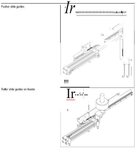
Remove any deposits on the springs (A).
Remove swarf residue with a brush. Apply oil the entire length of the springs using a brush.
Move the axes the entire length. Remove leftover oil, to keep it from
Move the axes the entire length. Remove leftover oil, to keep it from -
Has the spiral spring been cleaned as above, and are free of swarf?
-
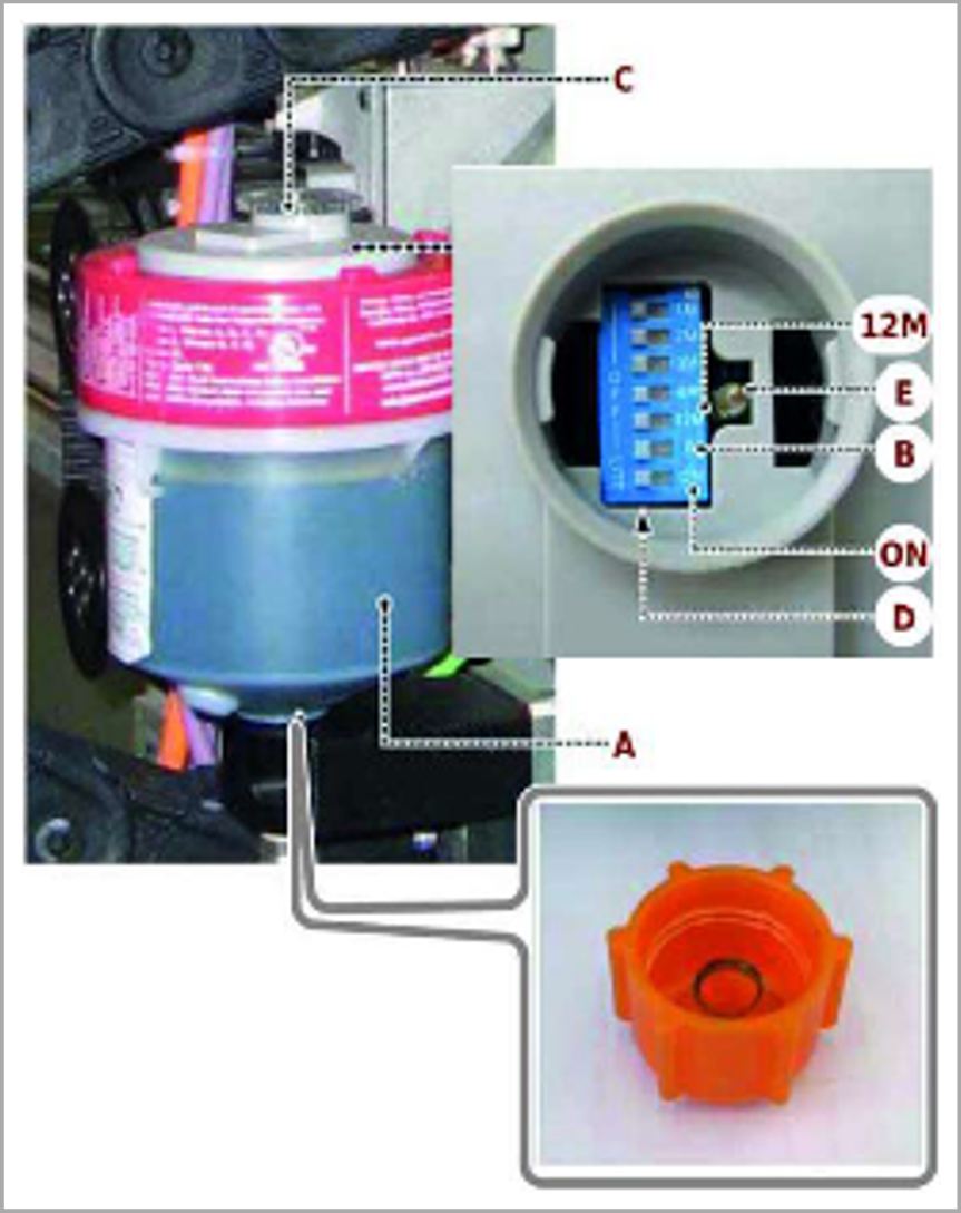
Check the liquid level in the jumbo luber rack lubricator.
Unscrew dispenser cartridge (A). Screw on the new cartridge after removing the bottom cap.
Unscrew the cover (C) and set the various functions by setting the switches (D).
Move the switch (12M) to on to set the amount of lubricant dispensed and therefore the frequency for replacing the dispenser.
When finished, the cartridge must be replaced every 12 months
Move the switch (on) activating the pump to on. (This activates the dispenser).
If necessary, enable the led (E) moving the switch (B) to on.
When enabled, it signals pump operation, flashing each time it dispenses
The lubricant level is visible through the level window in the container.
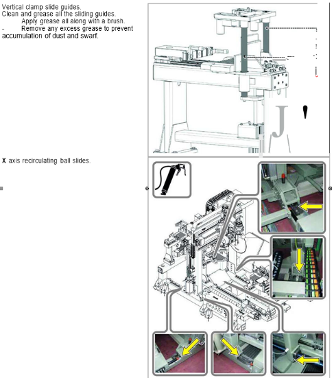
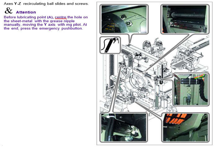
Lubrication of guideways of the other axes is performed via grease nipples, see "Greasing points diagram".
The other switches must remain set to "OFF".
Use a grease gun to inject grease into the grease nipples shown on the greasing points diagram. Continue to inject grease until it seeps out thus ensuring that the original grease has been replaced -
Has the cylinder fixing bolts been inspected and tightened if needed?
-
Lubrication levels sufficient?
-
Greasing Points Diagram
-
Greasing Points Diagram
-
Greasing Points Diagram
-
Greasing Points Diagram
-
Greasing Points Diagram
-
Have the grease points been fully lubricated?
-
This machine uses pliers for locking the tool; when you have to install or change it, it is necessary to pay attention that the straight shank has the same diameter of the pliers, so, if necessary, it is necessary to replace the pliers (A) loosening the ring nut (B) and proceeding as described below.
set the main switch to OFF.
Trigger the pliers (A) in the ring nut (B) in such a way that it is straight and concentric.
screw the ring nut (B) on the spindle (C)
without tightening.
Insert the shank of the tool (clean) (D) in the collet (A), for the weldon collet block the tool with the screw (F).
Insert the hex key in the spindle surface
(E) and that of the segment in the ring nut (B).
Keeping the key of the spindle blocked, turn that of the ring nut clockwise for it to block. -
Has the tooling been replaced?
-
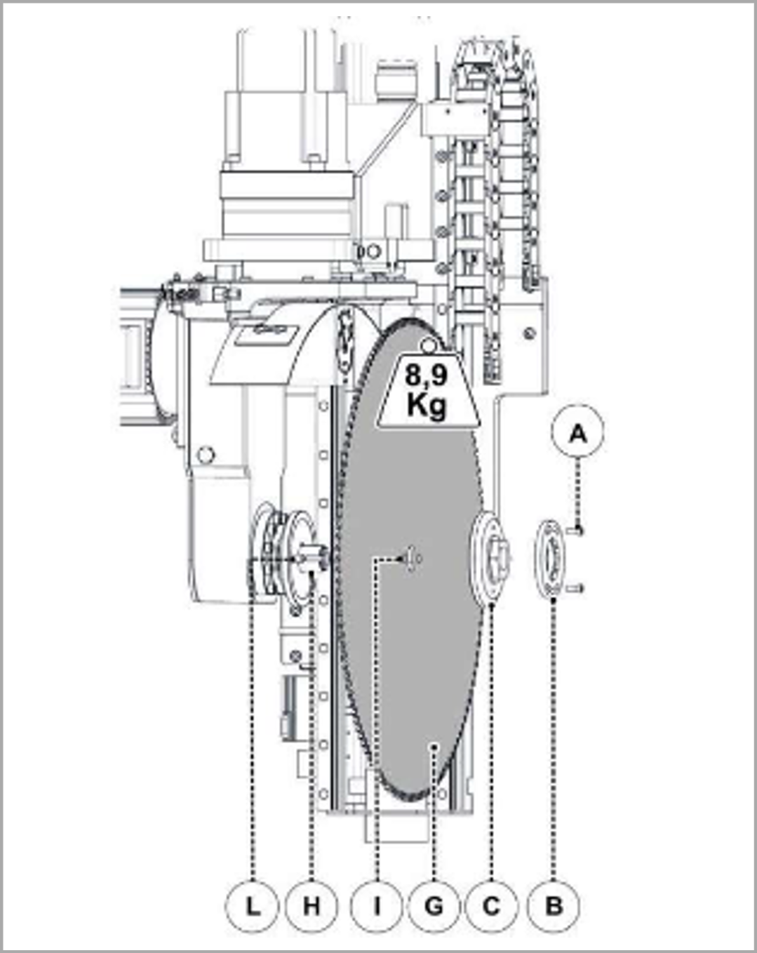
***Before proceeding, look through the transparent parts of the cabin and make sure that the blade to be replaced is stopped***
Use only the original blades intended for this type of machine model.
Use adequate protective gloves for all these operations.
The blade is very heavy, the weight of which can be found on the tool table and on the specifications of the spare blade.
Get ready to support this weight when disassembled, assuring the stable balance of the operator and a sure hold of the tool.
The blade must be replaced with the machine off and the electric master switch and the pneumatic isolator valve switch padlocked.
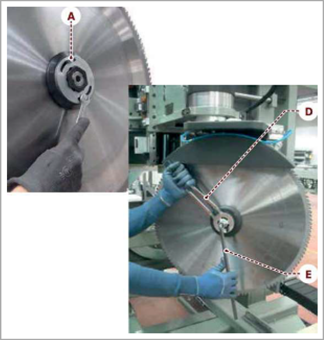
Switch the machine off as described in the chapter "switching machine off". Loosen the screws (A).
Remove the retaining ring (B). -
Keeping the nut (C) still with the spanner
(D) , turn the blade shaft with the hex key
(E) the opposite direction to blade rotation.
Remove the nut (C).
Take out the blade(G) and replace it. Reassemble the blade after having thoroughly cleaned the blade holder shaft (H), the flange it rests on and the front flange.
Centre the reference holes (I) on the blade with the pins (L).
Danger
Before restarting the machine , make sure that the blade has been blocked and the doors of the cabin closed correctly, checking that the microswitch is connected properly. -
Have the blades been replaced?
-
The operations described in this chapter depend on the mechanical maintenance technician.
The tasks depending on the operator are indicated in chapter "operators in charge of the machine".
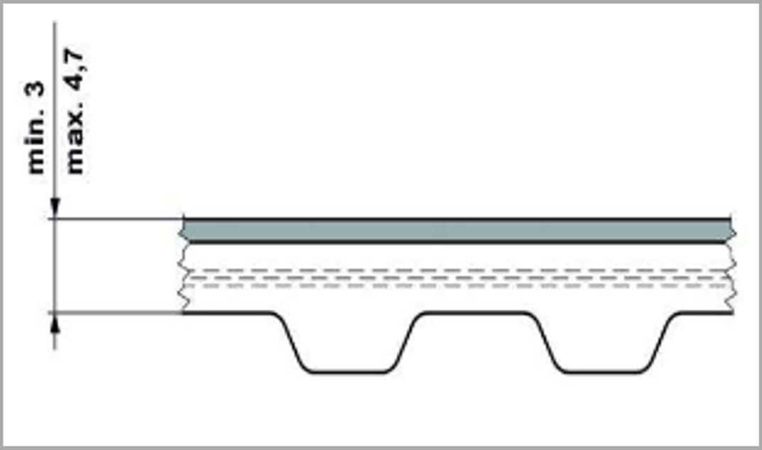
Inspect the top of the belt and the teeth for wear.
A) min 3 mm .
B) max 4, 7 mm. -
Does the belt need replacing?
-
Have you replaced the belt?
-
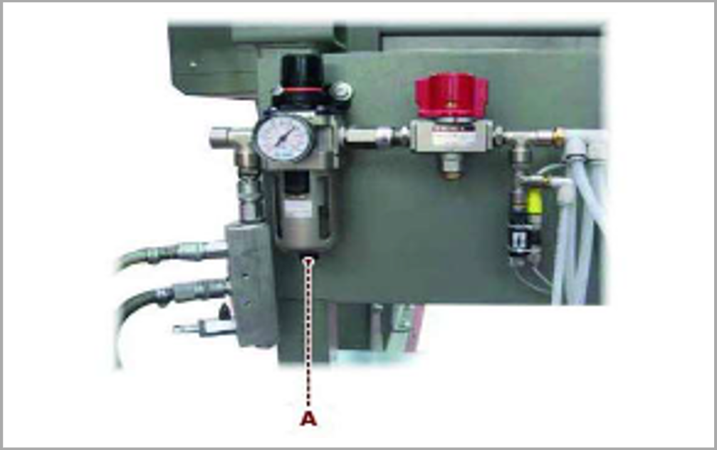
The condensation is drained out manually
Press button (A) under the collection bowl to discharge condensate manually .
CHECK!
The operating pressure of the following units is: FR unit with inlet pressure of 6,5-7 bar . pressure switch setting of 4 bar.
(±0,2 bar tolerance) . -
Maintenance Of Compressed Air System Complete?<br>
-
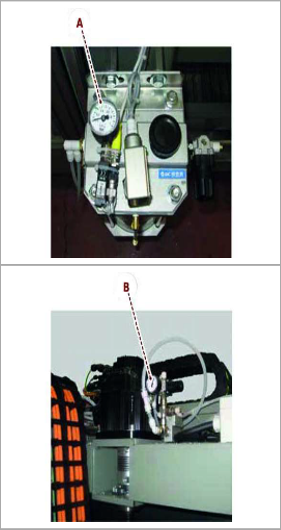
CHECK!
The operating pressure of the following units is:
A) Coolant oil tank pressurisation device, between 3 and 4 bar (0,3+0,4 MPa).
B) Z axis balancing unit, equal to 5 bar
(0,5 MPa).
The pressure of the concerned units and devices is adjusted when the machine is activated and must not be changed.
Pressure values different from those indicated in this paragraph could point out a failure in the pneumatic system. Before performing adjustments, contact the technical assistance service.
Check that the pneumatic circuit lines and connector are in good condition and airtight. check that cables are in good condition and that the electrical connectors are firmly secured.
-
Pneumatic System and Connection Check Complete?

General House Keeping
-
Has the area around the machine been fully cleaned?
-
Are the cleaning shadow boards populated?
Spares & Consumables
-
If Spares & Consumables have been used, have you emailed stores with a complete list for replenishment?
Finalisation
-
Has the service been completed?
Comments
-
Anything else to report?
-
Note