")


Title Page
-
Inspected by
-
Inspection date
Observations
-
Has there been any reports of any air leaks?
-
have you Identified the area of leak before isolating the power and/or air?
- Yes
- No
- N/A
Safety
-
Electricity - Have you Isolated the Power? (LOTO)
-
have you discharged any stored/potential electrical energy?
-
Compressed Air - Have you isolated the compressed Air?
-
Have you discharged any stored/potential air? (LOTO)
-
Have you filled out as LOTO check sheet?
-
Is there sufficient lighting in the area?
Preparation
-
Confirm The Serial Number Of The Machine S/N: xxxxxxx
-
Do you have all the relative tools, consumables and checking equipment to perform the service?
-
Are you wearing all the required PPE?
-
Do you have a safe working area?
Running Maintenance
-
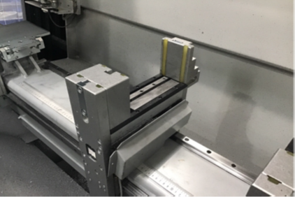
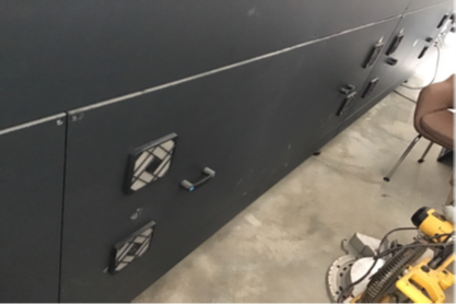
One of the most common used areas of this machine are
the Clamp Stations.
These must be kept clean at all times, pro longing the life
term of the rubbers, moving parts, cylinders, bearings and
the air brakes -
Clamp stations Cleaned?
-
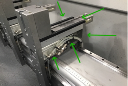
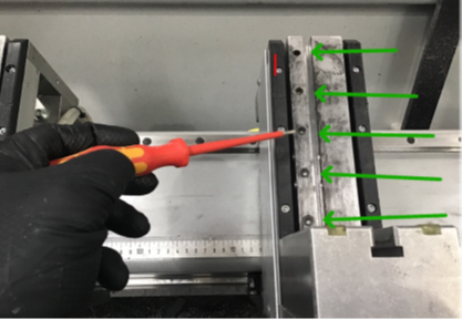
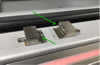
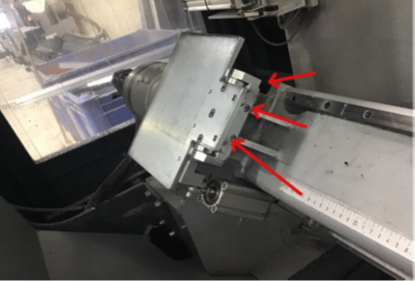
Remove the side covers of each clamp and clean out, an
airline can be used with a regulation to 2 bar. This is
sufficient enough to blow the area out and removes swarf.
Arrows indicating where areas need special attention for
clean out. -
Did you remove the side covers of each clamp and clean out any swarf?
-
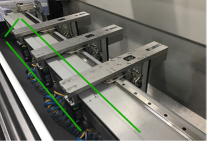
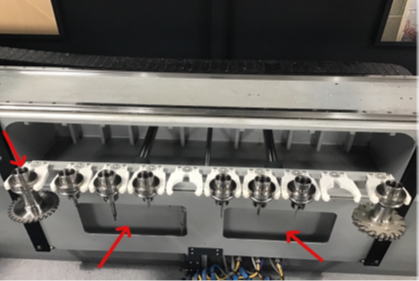
Turn the A axis to +90 and inspect and clean out the the rack in
which the motor gears travel on.
This should be kept dry, do not grease and should be
Swarf free, as the Swarf can collect inside the rack teeth
and damage the alignment between rack and gear. -
Has the rack (where the motor gears run) been cleaned out?
-
Inspect the fixings of the clamp cables and ensure tie
wraps are fixed. -
Are clamp fixings in good working order?
-
You can also inspect the connectors and ensure these are
screwed tight. Only touch tight, do not over tighten. -
Are the connectors screwed tight?
-
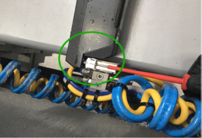
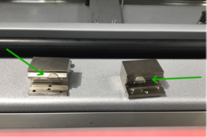
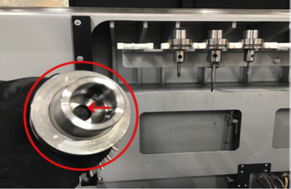
Inspect Clamp reflectors.
Inspect for damage and any oil contamination.
In this example you can see to the right (red arrow), Oil
has made its way into the reflector. This example is still ok,
but the problem this causes is that the clamp search sensor
can not identify the clamp at the calibration stage.
It is better to have a spare as spare parts. -
Are the clamp reflectors in good working order and free from damage and any oil contamination?
-
Next stage is to remove the cushion clamp blocks.
Strip the blocks and clean out, pay special attention to the
spring pins and use WD40 to lubricate. -
Have the spring pins been inspected and lubricated?
-
Rotate A Axis to -120 Degrees.
Inspect the cylinder fixing bolt, if needed, re tighten.
If these are loose essentially your profile can be loose
when machining! -
Has the cylinder fixing bolts been inspected and tightened if needed?
-
Ensure the clamp pin locations are fully cleaned out
Any Swarf in these, or the pins, can cause the pins not to locate correctly
resulting in damage to the blocks or the pin location bush
fittings. -
Have you inspected the pin locations and fully cleaned the areas of any swarf?
-
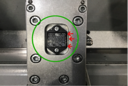
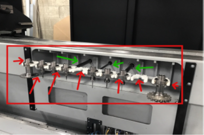
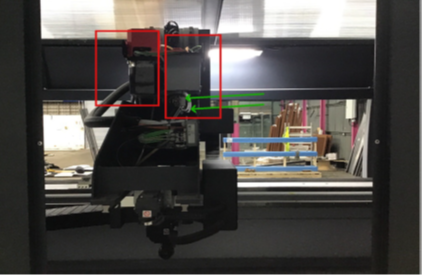
The Air brakes are one of the areas which can not be
cleaned everyday but you must service these every month, by removing. Swarf gathers here and forces the
motor to work harder when moving.
Unclamp the clamps for this operation! -
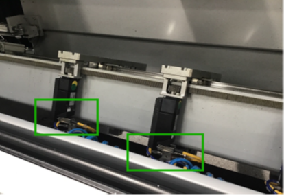
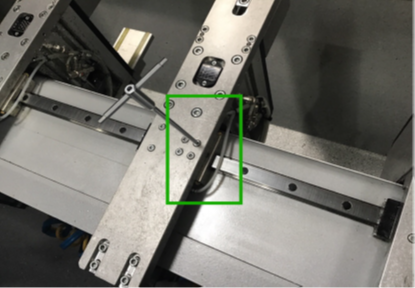
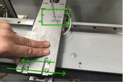
Pull the brake away
Remove the 2 air pipes top and bottom
Unscrew the 3 torque screw in the V shape (identified in
the green rectangle)
Be sure to not lose the Screws!!!! -
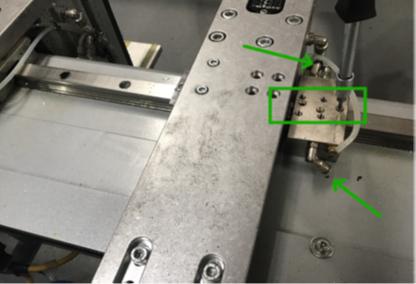
The unit then splits into 2 by sliding away from each other.
-
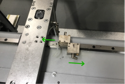
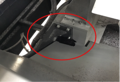
This is an example of the brake with the Swarf, you cant
even see the CAM in which pulls against the rail to brake.
This effectively cause problems for the motor having to
work harder just to travel along the rail. -
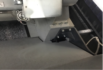
Example of a cleaned brake, see the difference!
Now you can see the CAMS! -
Before fitting the Brake unit (cleaned) you must also clean
the area in which the brake locates and fixes to. -
Repeat the removal process of the brake to refit.
1- Slide unit together on the rail
2- use the torque screw to fix together
3- Fit the air pipes to ensure the pipes ‘click’ into the
fittings.
4- slide the brake into position...
WHILST FIXING THE THE MAIN 4 CAP HEAD SCREWS
MOVE BACK AND FORTH THE FULL CLAMP UNIT.
This allows the brake to fix into position. -
Have you cleaned the air brakes
-
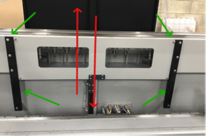
Clean black plastic ‘runners’. Use the Airline to clean and
apply WD40 lubricate.
Use the Tool change button on the console to move door
up,down. -
Have you cleaned the black plastic runners, and lubricated with WD40?
-
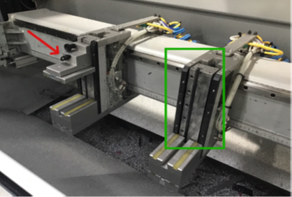
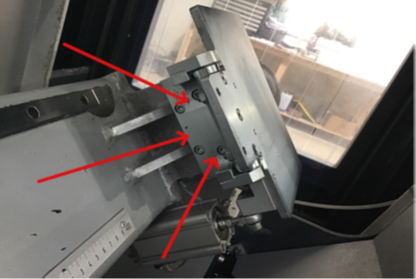
Green Arrows- Inspect and lubricate the cylinder Rails,
use WD40
DO NOT ALLOW WD40 ON TO THE TOOLING.
Red Arrows- Inspect the Plastic tool holders weekly for
wear, if tooling becomes loose, replace ASAP.
It is also ideal to have a spare plastic holder as spare parts
stock on site. -
Have you inspected and lubricated the tooling cylinder rails with WD40?
-
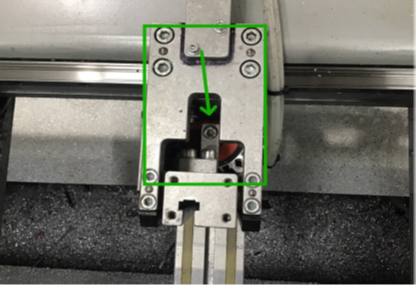
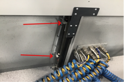
Inspect the tool change door sensors are fixed tight.
If loose the control can not identify if the door is in the
correct position which usually stops halfway through a tool
change cycle. -
Is the tool change door sensor tightly fixed?
-
This is an example of how the Tool change area should be
kept!
Clean tooling.
No damaged plastic clips.
Door inspection glass clean! So you can see the tools
inside the tool change area! -
Is the tooling glass door clean? you should be able to see the tools through the glass!
-
This is the tooling for AF310- HSK
Clean inside of each tool and also the outside, these parts
have fit inside the spindle! -
Has the tooling, and tooling area been cleaned?
-
Left Tank - X/Y/Z Lubrication Tank
Right Tank - Coolant
Please note when filling tanks at the very minimum press
Emergency Stop.
Lubrication Oil can be ordered through Parts.
Part number- 1007040
Coolant Oil must be ordered through customer services
Art Number- 264154 -
Has the X/Y/Z Lubrication tank level been checked, and topped up if needed?
-
Has the coolant tank been topped up?
-
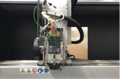
This is an image of the spindle area, and gives you an
idea of what is behind the cover! -
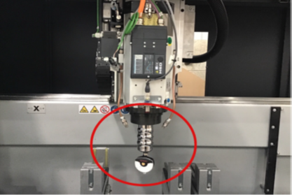
This an image of the spindle area without the cover and on
this occasion the clamp force is being inspected.
If tooling is not cleaned daily. Swarf travels into the spindle
and weakens the clamp force!!! -
Have you cleaned out the spindle area and is it no free of swarf?
-
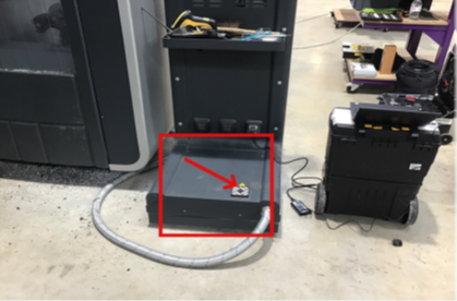
Remove filter and clean out
Remove cover (4 screws) -
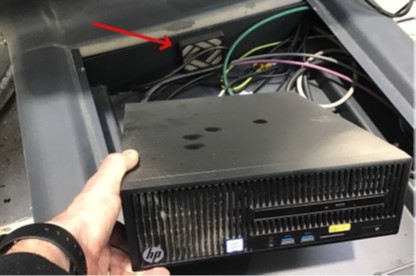
Remove internal cabinet filter and clean out.
-
Re-fit cover and fix screws
-
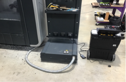
Have you cleaned out the Base unit area?
-
Have you vacuumed out the PC Base unit?
-
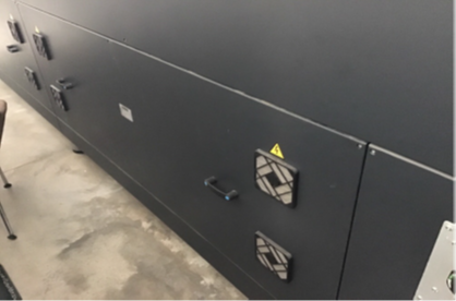
Remove all filters (x4) and blow out- monthly
-
Remove all filters (x4) and blow out- monthly
-
Have you cleaned out the rear of the router?
-
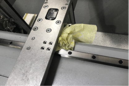
This is an image lower than the left stopper, this area must
be covered up as the manufacturer design has a hole for
cables to travel through. -
This is an image lower than the right stopper, this area
must be covered up as the manufacturer design has a
hole for cables to travel through. -
Can you confirm that the unused cable access port is covered?
-
Clean the area behind the stopper
-
Clean the area behind the stopper
-
Have you cleaned behind the stoppers?
-
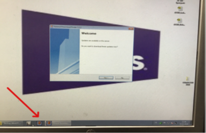
Software updates - GDF icon is usually pinned to the task bar, if not please
call Service Desk and request the GDF software be
installed and setup on the task bar. -
Are software updates available?
-
have you downloaded and installed the updates?
General House Keeping
-
Has the area around the machine been fully cleaned?
-
Are the cleaning shadow boards populated?
Spares & Consumables
-
If Spares & Consumables have been used, have you emailed stores with a complete list for replenishment?
Finalisation
-
Has the service been completed?
Comments
-
Anything else to report?
-
Note