


Information
-
Technician name: (First.Last)
-
Home office
-
Conducted on
-
Prepared by
-
Location
-
Personnel
IPT
1.) Preparation
-
Pre-arrival
-
Ensure professional appearance and conduct
-
Verify correct tools, equipment, and supplies
-
Review the work order
-
Pre-call the customer
-
During the pre-call introduce yourself and verify you are speaking the the account holder. Verify the address is correct, animals are restrained, someone over 18 will be present, and give the customer an ETA
-
Update appointment status to "Start"
-
Deploy your safety cones
-
Gather Materials: 1) Cell Phone 2) PPE 3) Boot covers 4) Toners 5) Receptacle tester 6) Inclinometer 7) Hand tools 8) SHS tote and brochure 9) CSAT flyer
-
Briefly look for line of sight *If potential LOS issue, skip to Step 4 after introduction with customer
2.) Customer Confirmation
-
-Introduction with customer -Put on boot covers -Confirm customer's order *Number of rooms to install *Equipment in each room (HD, SD, DVR) *Programming *Billing amount *Terms of commitment
Installation Planning (IJA steps 3 - 5)
TV1 Installation
-
Is this a Hopper job?
-
Where is the Hopper located?
-
Where is TV1 located?
-
What result did you have from your receptacle tester?
-
Hot neutral reverse. This is a fire hazard and we cannot install our equipment. Check the other nearby outlets for an acceptable reading.
-
The outlet has an open ground. Insert a 3 prong adapter and inform the customer. Notate the account in the "inside work performed" section of the work order.
-
Is TV1 Pre-wired?
-
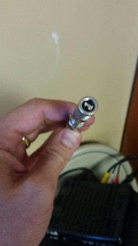
Does the barrel in the wall plate have a blue center?
-
Replace the barrel with a DNS approved blue barrel.
-
Did you replace the connector on pre-wired cable (and/or other side of barrel) if not an approved connector?
-
Replace the connector
-
Did you put Toner #1 (or brown) on the barrel for TV1/Hopper? <br>
-
Place toner on the cable.
-
Please proceed to next step of IPT
-
Determine the penetration for TV1 following the hierarchy below as:
Existing Penetration
Floor Penetration
Wall Penetration
Wall Fish -
What options do you have for potential Cable routes? Is there a home run box you can verify correct lines with the multiline Id? Is there a crawl space/attic/garage)? Prioritize entering the room at a point closest to the Rx locaton through the use of: 1. Interior wall fish 2. Interior wall penetration (room-to-room for TV2 back feed) 3. Exterior penetration 4. Room wrap
TV 2 Installation
-
Does the customer have internet? Where is the router located? If the customer doesn't have internet did you see if DishNet is a viable option for them, or when they are getting internet with another provider (set up a RTC with your manager if within 7 days)? If internet, did you plan connectivity into install using the hierarchy? What option did you choose: <br>
-
Is there a TV2 or Joey location?
-
Proceed to next step on the IPT
-
Did the outlets pass the receptacle test with two yellow lights?
-
Search for another outlet that passes or explain to the customer we cannot complete install until an electrician fixes their outlets.
-
Is the TV2/Joey location pre-wired with acceptable cable?
-
What options do you have for potential Cable routes? Is there a home run box you can verify correct lines with the multiline Id? Is there a crawl space/attic/garage)? Prioritize entering the room at a point closest to the Rx location through the use of: 1. Interior wall fish 2. Interior wall penetration (room-to-room for TV2 back feed) 3. Exterior penetration 4. Room wrap
-
Is the center of the barrel in the wall plate blue?
-
Continue down IPT to next step.
-
-
Replace the barrel with a DNS approved blue barrel.
-
Repeat TV2 section for all additional receivers
Grounding
-
What grounding component did you use?
- Electric meter panel & side clamp
- Metal conduit and galvanized strap
- Main house power grounding wire and split bolt
- AC disconnect box and side clamp
- Steel frame under house and I-beam clamp
- Not Grounded
-
Is grounding source 20' or less from ground block or node? <br>
Mounting and Peaking
-
What dish kit did you use for the installation?
- 1000.2 EA
- 1000.2 WA
- 1000.4 EA
- 500 DPP Twin
- 500+ DPP
- 1000+ DPP
-
What is the Azimuth and Elevation for the 110?
-
What is the Azimuth, Elevation, and Skew for the 119?
-
What is the Azimuth and Elevation for the 118.7?
-
What is the Azimuth Elevation and Skew for the 72?
-
What is the Azimuth Elevation and Skew for the 61.5?
-
What is the Azimuth and Elevation for the 110?
-
What is the Azimuth Elevation and Skew for the 119?
-
What is the Azimuth and Elevation for the 129?
-
What is the Azimuth and Elevation for the 61.5?
-
What is the Azimuth, Elevation, and Skew for the 72?
-
What is the Azimuth and Elevation for the 77?
-
What is the Azimuth and Elevation for the 110?
-
What is the Azimuth, Elevation, and Skew for the 119?
-
What is the Azimuth and Elevation for the 110?
-
What is the Azimuth, Elevation, and Skew for the 119?
-
What is the Azimuth and Elevation for the 118.7?
-
What is the Azimuth and Elevation for the 129?
-
Did you first go to grounding source before deciding on mounting location (must be within 20' of ground block)? <br>
-
To minimize cabling and increase the ease of the install you need to first look for mounting options as close to the ground source as possible.
-
Did you ensure mount is at least 10' away from power (lines and box, overhead and underground)?
-
You MUST be 10' away from all power. Find a location that is 10' away from power for your safety as well as to be within DNS guidelines.
-
Did you ensure clear line of sight for all orbitals?
-
Use your SAT BUDDY to identify you Azimuth and Elevation using the ZIP feature. Use your inclinometer to verify line of sight. You must have 5 degrees of clearance from all structures.
-
Which dish mount are you going to install?
-
Did you mount in a location requiring the least amount of cabling after meeting the above mounting requirements (allowing for the easiest installation)?
-
Did you ensure your mounting location meets all customer preferences?
Exterior Cabling
-
Which method did you use to run the cables into the house for each TV location?
- Used exsisting cable penetrations
- Floor pen (must
- Soffit pen into attic
- Gable pen into attic
- Wall Pen
- Slim line
-
Did you use the lines of the home and ensure the cabling is aesthetically pleasing?
-
Assure all lines are aesthetically pleasing. Cable should run in straight lines and hidden as much as possible.
-
Did you estimate the length of messenger cable needed to run from the dish to the ground block?
-
Did you estimate the length of ground wire needed to run from the grounding source to the ground block (must be less than 20')? <br>
-
Did you use only Hopper/Joey devices in the cable runs (taps, splitters, nodes, integrators, HIC) without violating the two-device rule?
-
Was the entire cable run inspected for unapproved components (barrels, connectors, splitters, diplexers, etc) and replaced with approved components if found?
Begin Installation (IJA steps 6 - 12)
6.) Dish Preparation
-
Set up work area in the back of your van
-
Load your tool belt and make sure you have the proper equipment for the install
-
Bring your tote with you to your job site because it is filled with all the components you will need
-
Cut and prep estimated messenger cable
-
Adjust skew and elevation (numbers gained from using ZIP function on meter)
-
Attach skew to reflector
-
Attach Y Bracket to the arm
-
Feed messenger up the arm and attach to the LNBF. Attach the LNBF tot he Y bracket
-
Assemble specialty mount if needed
-
Transport Materials
-
Gather SBSM, assembled dish, tote, and cable. Bring all materials to the mount site. Make a second van trip if ladder is needed
-
Locate the stud for the center of your footplate to attach to
7.) Dish Installation
-
Set up ladder. Two rungs if working from the ladder, 3 rungs if you are accessing the roof with a roof monitor
-
Level your mast side to side and up and down
-
Mark and pre-drill center holes
-
Apply silicone to the holes
-
Drive in center lag (3') 99% of the way
-
Verify mast is still level
-
Tighten center lags
-
Pre-drill and silicone all outer holes for all mount types except roof. Drive in and tighten remaining lags. wood wall 6 lags brick/cement 4 lags fascia 4 or 5 lags angled 6 lags
-
Tighten all hardware
-
Attach struts if needed, place dish on mast
-
Connect the SBSM and make sure you have the correct settings selected
-
Point and peak to optimal settings - Confirm with a push pull test
-
Lock dish down and perform limit scan
-
Take a picture of the completed mount.
8.) Grounding
-
Attach messenger wire to ground screw / lug / galvanized strap
-
Run messenger cable to ground block attaching cable every 12''-24''
-
Install ground block being sure to create 4'' drip loops and to torque all connectors to 30-in lbs
-
Connect messenger cable, messenger wire, and ground wire to ground block
-
Run ground wire to grounding component and connect
-
Take a picture of the ground block and ground source
9) Cabling
-
Is there existing exterior cable?
-
Use multi-line identifier to locate appropriate line
-
Connect DNS approved lines to proper components
-
Photos of all exterior cable penetrations
-
Use stud finder to locate studs
-
Identify a reference point for your exterior wall penetration. Use your measuring tape to measure from your reference point both inside and outside. Clear both entry and exit points. On the inside cut out an inspection hole and inspect for obstructions inside the wall. These steps will ensure you do not create a damage
-
Drill all penetrations (from inside to outside)
-
Feed cable through, add bushing, and apply silicone
-
Run remaining cables, attaching every 12''-24'' with clips, and connect to the proper components
Van Run #2
-
Gather equipment and clear any outside trash
-
Prepare interior cables
-
Return to van
-
Gather items. For interior work these items will be receivers, IP devices if this is a Hopper, phone, vacuum, Sat buddy, cable, wall fishing supply, ladder
-
Put on boot covers prior to entering the customers home
Interior cabling
-
Complete wall fish is applicable
-
Install any needed wall plates and then run the cable to the receiver making sure to attach the cable every 12''-24'' if needed
10.) Receiver installation
-
Check DBM and run limit scan at each receiver ensuring passing signal levels
-
Take picture of limit scan behind receiver
-
Unpack the receiver and install in a well ventilated area
Connect all the appropriate equipment.
-
Connect the receiver to the TV
-
Plug receiver into the power outlet
-
Proceed through the software download wizard. Continue to the next steps while the software is downloading
-
Prepare remotes : -Put on room labels and insert batteries - Enter TV code or power scan( hold [TV] continually hit [up arrow] when TV turns off hit [#]) -Limited mode (hold [TV] hit [page up] then hit [#]) -SAT auto tune TV2 (hold [TV] hit TV2 ch ex. [60] hit [#]) -Remote address (system info screen: hold [SAT] enter address # hit [#] then hit [RECORD])
-
Clean up all trash and receiver boxes
-
Be sure to use the vacuum to pick up small debris and ensure the customer gives you a 9 in clean up
-
Connect any TV2, Super Joey, or Joeys if applicable. If TV2 run channel scan, and if there are Super Joeys or Joeys connect and begin the downloads
-
Repeat for all TV locations
-
Activate all the receivers in ETAd on your phone
-
On hopper make sure all three tuners are downloaded and then send status. If Non Hopper move on to next step
-
Change screen format and resolution settings to appropriate settings
-
Verify all programming on all TVs
-
Enter any install notes for inside and outside work performed
11.) Customer Education
-
Explain all work completed to the customer
-
Explain SHS products focusing especially on surge protectors if there is none present
-
Hand the customer the remote
-
Use the Getting Started Guide for the remote and the DVR. On Hoppers make sure to explain the special features in the Hopper menu
-
Quiz the customer and have them recover from off input to ensure they understand. Take them to all the TVs in the house to show them working. Offer remote skins for multiple rooms to keep remotes in correct rooms
12.) Post Installation
-
Have customer sign agreements on phone
-
Ensure customer has no questions and thank them for choosing Dish
-
Ensure you have all the tools and equipment
-
Return to the van
-
Use the Log Out feature in comet and make sure all equipment is added and RAs verified. Complete the work order in ETA mobile
-
Depart
-
Signature stating the WO was completed to DNS standards
-
Email completed DIPT /DIJA to your ABM as well as Jason.Browder@drsinstall.com