Title Page
-
Job Name:
-
Job Number:
-
Footing Type:
- Traffic Signals
- Rate 3
- Rate 2
- ITS/Comms
-
Station No:
-
Site Location
-
ITP Lot Number
-
Conducted on
-
Prepared by
Pre-Construction Procedure
-
CB ENERGY ITP-028 - STREET LIGHT & TRAFFIC SIGNAL FOOTING INSTALLATION
-
Pre-Construction Procedure
-
Photo of construction drawing (title, page number, issue)
-
Risk assessment completed and construction drawings on site.
-
Have the exact location of existing underground and overhead utility services and other installations and/or roadside structures which may impact the footing location been confirmed?
-
Has all survey been completed including future kerb, pram ramps, light poles, finished levels and STOP bars
-
Materials
-
Has the entire cage been hot-dipped galvanised, including the threads? <br>(Galvanising standards used by manufacturer AS1650 – general galvanising & AS1214 – galvanising of threads)
Footing Location & Depth
-
Location of Footings
-
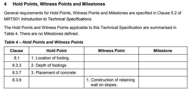
HOLD POINT #1<br>Has the location of the footings been approved by the superintendent prior to the excavation?<br>This includes - an underground services (DBYD) check<br> - clearances of overhead services<br>(MRTS92, Table 4, Clause 8.1)
-
Has the client advised of any non-standard footing depths?
-
Details of footing (Location, station no, footing type, reason, approval):
-
Additional photos of non-standard footings
-
Is the pole base correctly related to the pavement edge or running lines as shown on the construction drawings?<br>Will the orientation of the outreach match the construction drawings?
-
Photos taken of setout
-
If NO, give further details:
-
Depth of Footing
-
HOLD POINT #2<br>Has the excavation been inspected by the Administrator prior to the installation of the anchor cage?<br>The centre and invert location of the excavation has been surveyed and complies with the requirements in Clause 6.2, 6.3 and 6.4 of the TMR Surveying Standards.<br> (MRTS92, Table 4, Clause 8.3.3)
-
Add media
Footing Types
- Footing Type
-
Select
-
Road Lighting Footing Installation
-
Has the pole base been installed on the correct side of pits as per drawing?
Add Footing
-
Footing station number?
-
Footing type?
-
Conduit Size
-
Attach photo of the footing.
-
Rate 2 - Do the top of the treaded bars finish:<br>Major Road BPM 130 mm above FSL <br>Major Road SBM @-25 mm +/- 25 mm below FSL <br>Minor Road BPM 80 mm above FSL<br><br>Rate 3 - Do the top of the Deformed bars finish:<br>Major Road BPM 150 mm above FSL <br>Major Road SBM @-25 mm +/- 25 mm below FSL <br>
-
Is the relevant conduit central to the 4 bolts and a minimum of 200mm above concrete pour? (Slip or Fixed based)<br>Rate 2 40 mm Heavy Duty Conduit<br>Rate 3 50 mm Heavy Duty Conduit
-
Retaining Walls
-
WITNESS POINT #1<br>Where a road lighting is installed on slopes greater than:<br>a) 1:6 for slip base poles, or <br>b) 1:2 for fixed base poles<br>A retaining wall shall be constructed in accordance with the details shown on Standard Drawing 1382 or 1393, as appropriate.<br>
-
Has the construction of the retaining wall been Witnessed by the Administrator
- No additional inspection required
- YES - Superintendent to sign
- NO - Not onsite to inspect
-
Add signature
-
How was approval received?
-
Traffic Signals Footing Installation
-
For primary posts, mast arms and joint use poles, is the location of the post located a minimum of 0.5 m beyond the front edge of the stop line, irrespective of whether a marked foot crossing is provided or not. As per Austroads guidelines.
-
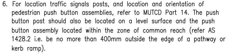
For posts with push buttons is the post position located within 400mm of the projected running line of the pedestrian crossing (not the outside of the wing) as per MUTCD Part 14, ref SD1447 note #6.
-
-
For posts and poles in centre medians<br>- Is the median a minimum of 1500mm wide as per BCC BSD4151 or <br>- Does the width of the island allow for the lanterns minimum clearance to kerb (300mm) as per MRD dwg 1428<br> ( check drawings for lantern type to be installed )
Add Footing
-
Footing station number?
-
Footing type?
-
Conduit Size
-
Attach photo of the footing.
-
Pedestal posts:<br>TMR / BCC installation - do the top of bolts finish 100mm above F.S.L as per MRD standard drawing 1421 or BSD4151<br>CoGC installation - do the top of bolts finish 90mm below F.S.L as per MRD standard drawing 1421 Rev. E
-
Joint use and BPM poles:<br>Do the deformed bars finish 150mm above FSL as per MRD drawing 1396 and 1392
-
Mast arm poles:<br>Do the deformed bars finish 190mm above FSL as per MRD drawing 1403
-
Is the 80mm HD or 100mm HD conduit central to the bolts and a minimum of 200mm above concrete pour? <br>Ref to MRD drawings 1421, 1403, 1396, 1428
-
Have the threads on deformed bars been protected (eg was insulation tape applied to threads)?
Concrete Mix Design & Acceptance
-
Concrete Mix Design & Acceptance
-
Has the concrete mix type been checked and quantity of concrete calculated before placing concrete ordered?
-
Has a concrete tester been booked with the concrete as per MRT 70 13.3 sampling?
-
Are weather conditions suitable for the amount of concrete that is planned to be poured
-
If a special class mix is used, ready-mixed concrete shall be placed and compacted within 1 hour of charging the mixer for concrete temperatures up to 32°C and within 45 minutes of charging the mixer for concrete temperatures exceeding 32°C but less than 35°C. as per MRTS70<br><br>If Normal class concrete is used, placement time to be within 90 minutes of batching and temperature not greater than 35deg
Concrete Placement
-
Placing Concrete
-
HOLD POINT #3 The concrete shall not be placed until the excavation, formwork and anchor cage, rag bolt assembly or holding down bolts have been inspected by the Administrator (MRTS92, HP#3 Table 4, Clause 8.3.7) (MRTS70, HP#12 Table 5.1(d) Clause 17.11.1)
- No additional inspection required
- YES - Superintendent to sign
- NO - Not onsite to inspect
-
Photos of footing
-
Superintendent Signature:
-
Photos of footing
-
If NO, what type of inspection has been excepted...
- Phone / Verbal
- Pre approved
- Photographic
- No inspection required
-
Photos of footing
-
Ready-mixed concrete shall be placed and compacted within 1 hour of charging the mixer for concrete temperatures up to 32°C and within 45 minutes of charging the mixer for concrete temperatures exceeding 32°C but less than 35°C. as per MRTS 70
-
Have traffic conditions from batching plant to job site been considered. <br>This shall also include actual site T/C conditions.
-
WITNESS POINT #8 Has the concrete placement been witnessed by the Administrator or TMR representative? (MRTS70 Table 5.1(d) Cl 17.11.1)
- No additional inspection required
- YES - Superintendent to sign
- NO - Not onsite to inspect
-
-
Add signature
-
If NO, what type of approval to pour has been received...
- Phone / Verbal
- Pre approved
- Photographic
- No inspection required
-
Have the footings been constantly vibrated as the concrete was poured?
-
Photo of orginal copy of delivery docket.
-
Have all footings had the concrete finished off, ensuring that all deformed bars are covered?<br>Has any concrete overflow been cleared of the footing?
-
Photos of footings after concrete pour.
-
Has the site has been left clean and safe? Barricading installed where required?
-