


Fire Suppression Systems–Chubb Level 2 Service
-
VDAS Loss Of Pressure (LOP) Fire Suppression System
-
Maintenance Service Record in accordance with AS5062.
Customer Details:
-
Customer
-
Location:
-
Date:
-
Machine ID No:
-
Machine Type
-
Machine Model
-
Purchase Order No:
-
Work Order No:
LOP 12 Monthly Service Sheet
-
Is the Equipment Serviceable?
- Compliant
- Non-Compliant
- N/A
-
Can the System be repaired
-
Parts used to repair system
Fire System Information
-
Cylinder Size
-
Water quantity 16 lt. / Foam 2 lt.
-
Water quantity 21.5 lt. / Foam 2.5 lt.
-
Water quantity 31lt. / Foam 4 lt.
-
Water quantity 44 lt. / Foam 6 lt.
-
Water quantity 75 lt. / Foam 10 lt.
-
Verify and record the cylinder(s) manufacture date. If this exceeds five years old then the cylinder will require an inspection and hydrostatic test in accordance with AS2030.5 and AS2337.1.
-
Confirm and ensure all cylinder(s) bracket bolts are tight and bracket(s) are in a serviceable condition.
-
Nozzle Quality
-
Alarm Panel Type
Discharge Test
-
An annual discharge test can be used to confirm the complete PEFS F3 system operates and performs as that
intended as when originally commissioned.
Please refer to the Chubb PEFS F3 Vehicle Fire Suppression System SDS prior to carrying out the Discharge Test.
Discharge of foam solution must be handled according to national or local waste regulations. Permission must be
granted from the site representative before carrying out the discharge test. -
Check system pressure is reading in the green sector on the pressure indicators located on the cylinder valves and manual actuators.
-
Discharge the PEFS system using the furthest located LOP manual actuator. Please follow local/state government and site specific requirements and procedures - Refer to the foam change out procedure if required. Record discharge time and observe nozzle area coverage (seconds) and compare it to the EDT recorded during commissioning.
-
Confirm all nozzles discharge and produce conical spray pattern.
-
Check that all monitoring and control panel alarms, shutdown and ancillary functions operate as intended
-
Engine shutdown delay test completed, Record shutdown delay (seconds)
-
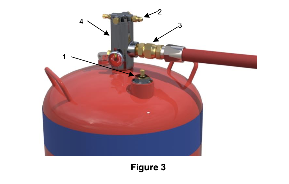
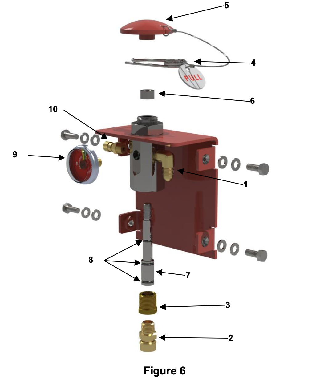
After discharge test has been performed ensure that the system is fully degassed. Degas the circuit by depressing the core of Schradder Valve. Check that the pressure indicator on LOP Cylinder Valve (4) shows 0kPa
Storage containers
-
-
Remove discharge hose (3) from cylinder valve (4).
-
Remove actuation hose (2) from top of cylinder valve (4).
-
Remove filler port assembly (1)
-
Remove foam solution from the cylinder.
-
Check all cylinder burst disk assemblies are not damaged. Use of a vinyl protective cap over the burst disk assembly is recommended to prevent ingress of dirt and wear on the burst disk surface.
-
Visually inspect exterior of all installed cylinders. Where a cylinder is dented, scored, pitted or otherwise damaged by corrosion and it cannot be determined if the damage is within the limits as detailed in AS 2337.1, then the cylinder shall be condemned.
-
Visually inspect interior of all installed cylinders. Where a cylinder is damaged by corrosion and it cannot be determined if the damage is within the limits as detailed in AS 2337.1, then the cylinder shall be condemned.
-
Re-fit and secure cylinders into brackets.
Cylinder Valve – Service
-
WARNING: The cylinder is a pressure vessel. Do not remove any parts from the cylinder prior to depressurising the cylinder.
-
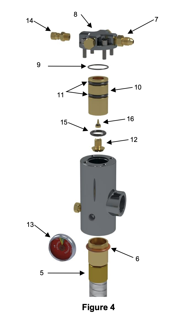
1. Remove cylinder valve (4) from cylinder.<br>2. Remove Syphon Tube (5) and Cylinder Neck O-ring (6)<br>3. Remove the 4 screws and washers (7).<br>4. Remove the cap (8) and o-ring (9).<br>5. Remove the piston assembly (10).<br>6. Inspect and clean piston o-rings (11) and sealing o-ring (15). Replace if they show signs of wear or damage.<br>Check to ensure check valve (16) moves freely inside piston, clean and or replace if required. Lubricate outside diameter o-rings (11) and outside diameter of piston assembly (10) with Molykote 111. Do not lubricate sealing<br>o-ring (15) and check valve o-ring (16). If retainer (12) was removed, re-fit using Loctite 569 or Loctite 577 on thread.<br>7. Clean inside of valve. Check for scratches and scoring. Re-install piston assembly (10).<br>8. Inspect and clean o-ring (9) and replace if it shows signs of wear or damage. Lubricate o-ring (9) with Molykote 111 and fit to cap (8).<br>9. Re-install cap (8), washers and screws (7) to cylinder valve.<br>10. Inspect syphon tube (5). Replace if tube has become stiff or is damaged.<br>11. Inspect and clean Cylinder Neck O-ring (6) and replace if it shows signs of wear or damage. Lubricate with Molykote 111.<br>12. Inspect and clean Pressure Indicator (13) and Schrader Valve (14). Replace if faulty or damaged. Use Loctite 577 or Loctite 569 on threads<br>13. Re-install cylinder valve (4) to cylinder.
-
Additional requirements if LOP Valve Actuation Bypass is installed:
-
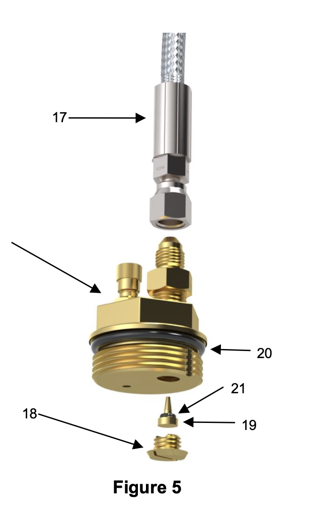
1. Remove hose assembly (17) from filler plug assembly (1)<br>2. Remover filler plug assembly (1) from cylinder<br>3. Unscrew retainer (18) and remove check valve (19)<br>4. Inspect and clean oring (20) and check valve oring (21). Replace if they show signs of wear or damage. Do<br>not lubricate check valve o-ring (21).<br>5. Re-fit retainer (18) using Loctite 243 on thread. Only use a small dot of Loctite as shown below. Allow to<br>cure for at least one hour.
Cylinder Refilling
-
WARNING: The cylinder is a pressure vessel. Do not remove any parts from the cylinder prior to depressurising the cylinder.
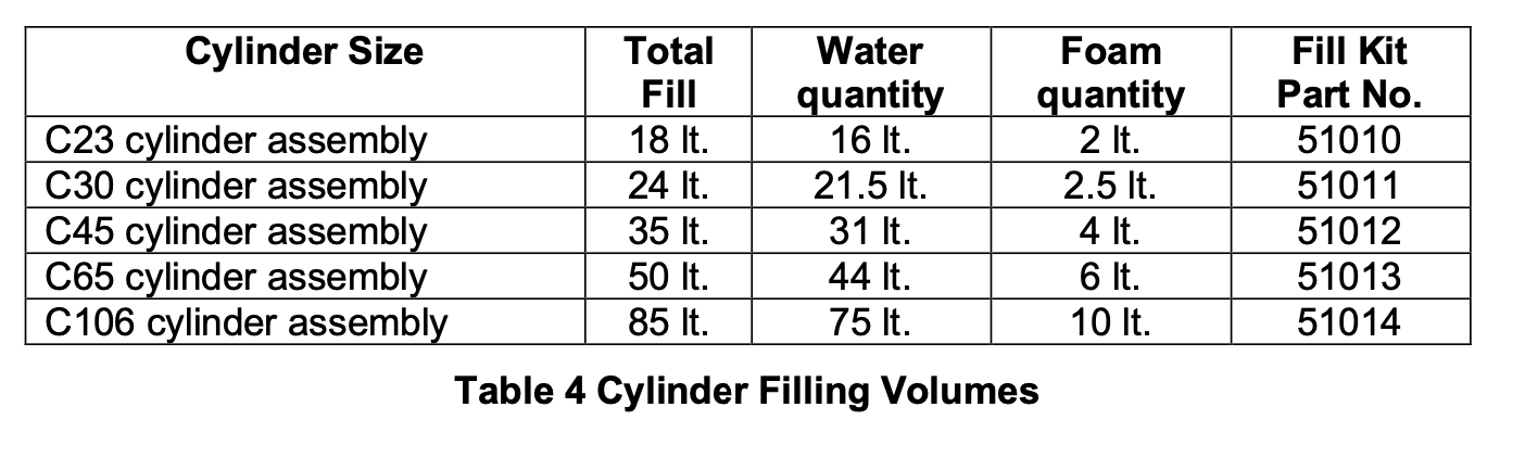
Cylinders must only be filled with clean potable water (chloride ion content <150ppm). The fill quantities for each size cylinder are detailed in the table below.
Please refer to the Chubb PEFS F3 Foam Concentrate SDS prior to handling the foam concentrate. -
1. Remove Filler Plug Assembly.<br>2. Filling by Scales:<br>a. Remove Over-fill tube (if fitted) from filling port.<br>b. Fill cylinder with water to required volume as per Table 4 Cylinder Filling Volumes<br>c. Add complete contents of foam from the Filling Kit.<br>3. Filling by Over-fill tube (LOP valve must be fitted to cylinder in closed position):<br>a. Ensure Over-fill tube is correctly seated in filling port.<br>b. Add water to cylinder until it initially over-flows. (Do not insert water supply hose below the bottom of the Over-fill tube.)<br>c. Remove Over-fill tube from filling port.<br>d. Add complete contents of foam from the Filling Kit.<br>4. Screw the PEFS F3 Mixing Tool onto the cylinder neck ring (hand tight) and attach a drill to the shaft. Mix for at least 3 minutes on slow speed setting.<br>5. Refit the Valve Assembly and Filler Plug Assembly.
Distribution System – Clear Passage Test
-
1. Disconnect discharge hose from cylinder valve.<br>2. Remove Nozzle Foil Caps from nozzles.<br>3. Flush discharge network with water and/or compressed air/nitrogen<br>4. Check distribution network is clear of any blockages<br>5. Clean Nozzles and Shrouds.<br>6. Re-fit Nozzle Foil Caps. Replace foil caps if required.<br>a. Foil Caps should only be fitted and removed using the Nozzle Cap Tool. The recommended torque setting is 4-5Nm.<br>b. When replacing Foil Caps additional Wave Washers are required to be added behind the shroud so that there is a total of five wave washers fitted.<br>c. Always screw on the Foil Caps by hand for the first couple of turns before using the Nozzle Cap Tool to tighten the cap to prevent cross threading.<br>7. Check nozzles are pointing at pre-determined aiming points. Refer to system design data (baseline data) as of last commissioning.<br>8. Check distribution system is intact and not damaged:<br>a. Hoses are not worn, split, cut or kinked.<br>b. Hoses have protective sleeves fitted along locations where rubbing can occur.<br>c. Tubing is not dented, kinked or otherwise damaged<br>d. Fittings do not show signs of excessive corrosion<br>e. Fittings are secure.<br>f. Clamps are adequately secured to the equipment and firmly hold the discharge hoses and or tubing in place.<br>g. Nozzle brackets (where fitted) are adequately secured to the equipment and firmly holds the nozzle kit fittings.
Manual Actuators – Service
-
WARNING: Do not loosen any hose connections or fittings in the LOP actuation system while the system is
pressurised. This will cause the system to discharge. Prior to servicing any LOP actuators ensure the system is
depressurised by depressurising the PEFS F3 cylinders using the Schrader valve fitted to the cylinder Filler Plug
Assembly. Ensure pressure indicators on manual actuator reads zero pressure. -
1. Remove the actuator cover plate.<br>2. Remove actuation hose from actuator connection (1).<br>3. Remove Foil Nozzle (2) and Adaptor (3)<br>4. Check the Foil Nozzle (2) to ensure its foil seal is intact and not damaged or ruptured. Replace if required.<br>5. Remove Pull Pin (4)<br>6. Remove Push Button (5) and Nut (6)<br>7. Remove valve piston assembly (7) from valve body.<br>8. Inspect and clean piston o-rings (8) and replace if they show signs of wear or damage. Lubricate using Molykote<br>111.<br>9. Refit valve piston assembly (7) to valve body<br>10. Ensure that the actuation mechanism moves freely.<br>11. Refit Nut (6) and Push Button (5). Tighten nut up against Push Button.<br>12. Refit Pull Pin (4)<br>13. Refit Adaptor (3) and Foil Nozzle (2). Use Loctite 577 or Loctite 569 on threads<br>14. Inspect and clean Pressure Indicator (9) and or Schrader Valve (10). Replace if faulty or damaged. Use Loctite<br>577 or Loctite 569 on threads<br>15. Reconnect actuation hose to actuator connection (1).
Detection system – Pneumatic
-
WARNING: Do not loosen any hose connections or fittings in the LOP actuation system while the system is
pressurised. This will cause the system to discharge. Prior to replacing any LOP detection tubing ensure the system
is depressurised by depressurising the PEFS F3 cylinders using the Schrader valve fitted to the cylinder Filler Plug
Assembly. -
After having depressurised the PEFS F3 system:<br>1. Replace each length of LOP detection tubing.<br>2. Ensure LOP tubing does not kink.<br>3. Check LOP tubing is located in correct position. Refer to system design data (baseline data) as of last commissioning.<br>4. Check to ensure any modifications to equipment has not subjected LOP tubing to possible heat exposure greater than 90°C.<br>5. Check LOP tubing fittings do not show signs of excessive corrosion.<br>6. Check LOP tubing fittings are secure.<br>7. Check LOP tubing clamps are adequately secured to the equipment and firmly hold the LOP tubing in place.
Actuation system – Pneumatic
-
WARNING: Do not loosen any hose connections or fittings in the LOP actuation system while the system is pressurised. This will cause the system to discharge. Prior to replacing any detection fittings or hose ensure the system is depressurised by depressurising the PEFS F3 cylinders using the Schrader valve fitted to the cylinder Filler
Plug Assembly. -
Check pneumatic actuation system is intact and not damaged:<br>1. Hoses are not worn, split, cut or kinked.<br>2. Hoses have protective sleeves fitted along locations where rubbing can occur.<br>3. Fittings do not show signs of excessive corrosion<br>4. Fittings are secure<br>5. Manifold block is adequately secured to the equipment.<br>6. Clamps are adequately secured to the equipment and firmly hold the actuation hose in place.<br>7. Carry out clear passage test on all actuation hoses:<br>a. Disconnect actuation hoses from cylinder valves (and bypass kit if fitted)<br>b. Disconnect all actuators - manual, electrical and LOP Detection Tubing<br>c. From the manifold block:<br>i. Disconnect each actuation hose<br>ii. Flush each actuation hose with dry compressed air/nitrogen.<br>iii. Check each actuation hose line from the manifold block is clear of any blockages and moisture.<br>iv. Check manifold block is clear of any blockages and moisture<br>v. Reconnect each actuation hose onto manifold block.<br>d. Reconnect all actuators - manual, electrical and LOP Detection Tubing.<br>e. Leak test the LOP actuation network prior to making the actuation hose connections to the cylinder valve(s).
Actuation system – Electrical [where fitted]
-
Note: The following maintenance activities should be carried out in conjunction with the listed fire control system
manuals. -
1. Check electric actuation system is intact and not damaged:<br>a. Electrical cabling is not worn, split, cut or kinked.<br>b. Electrical cabling has protective sleeves fitted along locations where rubbing can occur.<br>c. Electrical connectors are intact and not damaged.<br>d. Separate connectors and check to ensure they are free from ingress of dirt, water and corrosion. Replace<br>if required. Re-connect all electrical connectors.<br>e. All cabling clamps and supports are adequately secured to the equipment and firmly holds the cabling in place.<br>2. Function test all actuation circuits. Ensure each LOP Electric Actuator opens and closes correctly.<br>3. Check all wiring for earths
Detection system - Electrical [where fitted]
-
Note: The following maintenance activities should be carried out in conjunction with the listed fire control system
manuals. -
1. Check electric detection system is intact and not damaged:<br>a. Electrical cabling is not worn, split, cut or kinked.<br>b. Electrical cabling has protective sleeves fitted along locations where rubbing can occur.<br>c. Electrical connectors are intact and not damaged.<br>d. Separate connectors and check to ensure they are free from ingress of dirt, water and corrosion. Replace<br>if required. Re-connect all electrical connectors.<br>e. All cabling clamps and supports are adequately secured to the equipment and firmly holds the cabling in place.<br>f. Detector locations are in correct position. Refer to system design data (baseline data) as of last commissioning.<br>2. Function test all detectors<br>3. Check all wiring for earths
System interface and shutdown [where fitted]
-
Note: The following maintenance activities should be carried out in conjunction with the listed fire control system
manuals. -
Test all fire suppression system activated equipment shutdowns and record delay time.
System Pressurising
-
LOP systems are pressurised using the Schrader valve fitted on top of the LOP Valve Assembly or using the Schrader valve fitted on the manual LOP actuators.
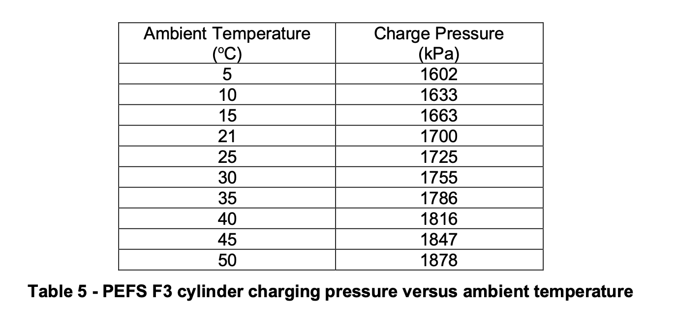
WARNING: Do not pressurise a cylinder that is not in test date. -
NOTE: Do not pressurise LOP systems using the schrader valve on the filler port assembly of the PEFS cylinders.<br>This will cause the cylinder to discharge.<br>1. Cap the discharge port of each cylinder valve to prevent solution loss in the event of an accidental discharge.<br>2. Check to ensure that all electrical actuation devices have been isolated.<br>3. Connect a regulated source of nitrogen through an approved charging rig (refer Figure 7) to either:<br>a. the cylinder valve assembly charging point<br>b. the charging point on one of the LOP manual actuators<br>4. Pressurise the system to the correct listed pressure as per Table 5.<br>5. Hold pressure for a minimum of 1 minute. Increase this time for each additional cylinder.<br>6. Check the pressure indicator on the cylinder valve and ensure it reads in the green sector<br>7. Shut off supply at the control valve and unscrew the charging adaptor (internal)<br>8. Vent pressure from the charging rig prior to disconnecting adaptor then disconnect the pressure source.<br>9. Test the actuation system for leaks. Leak testing should be carried out using a liquid leak detection solution.<br>a. Leak test all fitting connections<br>b. Leak test all LOP Manual actuators (refer above under 6 Monthly Service Instructions)<br>c. Leak test all LOP Electrical Solenoid Valve Assemblies<br>10. Test the cylinder for leaks. Leak testing should be carried out using a liquid leak detection solution.<br>a. Leak test filler port<br>b. Leak test burst disk<br>c. Leak test all ports on the LOP Valve assembly<br>d. Leak test cylinder welds.<br>11. Remove caps from discharge ports and re-fit distribution hoses.
After Maintenance Activities
-
After all Yearly maintenance activities have been completed:
-
1. Ensure all pressure indicators are reading in the green zone.
-
2. Ensure all labels are in good condition (refer 6 monthly service item 8)
-
3. Ensure control panel (where fitted) is reset to its normal operation mode and is no longer in its “Isolation / Test” mode.
-
4. Ensure panel status lights are in normal condition (refer 6 monthly service item 2)
-
5. Complete routine service records in accordance with AS5062
-
6. Stamp Service Tag with the number “2” in the corresponding Year/Month location.
Labour time:
-
Labour
Further repairs required:
-
Comment:
Sign Off
-
I Hear by certify that the above system has been in accordance with AS5062 and the information on this service record is true and correct
From PIRTEK
-
Pirtek Centre Name:
-
Technician Name:
- Ashley Lawson
- Chris Paton
- Peter Eversham
- Tim Eversham
- Nick Stallard
- Coedy Kleinig
-
Cert Number: QTEC L1083
-
Email: Ashley@pirtekeme.com.au
-
Position: Service Technician
-
Cert No: L1084
-
Email: Chris@pirtekeme.com.au
-
Position: Service Technician
-
Cert No: E-086
-
Email: Peversham@pirtek.com.au
-
Position: Service Technician
-
Cert No: E-0146
-
Email: Teversham@pirtek.com.au
-
Position: Service Technician
-
Cert No: L0963
-
Email: Nick@pirtekeme.com.au
-
Position: Service Technician
-
Cert No: L0958
-
Email: Coedy@pirtekeme.com.au
-
Position: Service Technician
-
Signature:
From Customer/End User
-
Name
-
Signature:


