


Fire Suppression Systems– FSI Level 2 Service
-
VDAS Loss Of Pressure (LOP) Fire Suppression System
-
Maintenance Service Record in accordance with AS5062.
Customer Details:
-
Customer
-
Location:
-
Date:
-
Machine ID No:
-
Machine Type
-
Machine Model
-
Purchase Order No:
-
Work Order No:
LOP 12 Monthly Service Sheet
-
Is the Equipment Serviceable?
- Compliant
- Non-Compliant
- N/A
-
Can the System be repaired
-
Parts used to repair system
Fire System Information
-
Cylinder Size
-
Water quantity 11 lt. / Foam 1 lt.
-
Water quantity 15.5 lt. / Foam 1.5 lt.
-
Water quantity 28 lt. / Foam 2 lt.
-
Water quantity 46 lt. / Foam 4 lt.
-
Water quantity 84 lt. / Foam 6 lt.
-
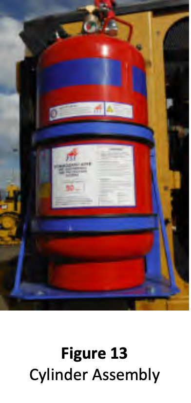
Verify and record the cylinder(s) manufacture date. If this exceeds five years old then the cylinder will require an inspection and hydrostatic test in accordance with AS2030.5 and AS2337.1.
-
Confirm and ensure all cylinder(s) bracket bolts are tight and bracket(s) are in a serviceable condition.
-
Nozzle Quality
-
Alarm Panel Type
FULL SYSTEM DISCHARGE
-
An annual discharge test can be used to confirm the complete PEFS F3 system operates and performs as that intended as when originally commissioned.
Please refer to the F3 Vehicle Fire Suppression System SDS prior to carrying out the Discharge Test.
Discharge of foam solution must be handled according to national or local waste regulations. Permission must be granted from the site representative before carrying out the discharge test. -
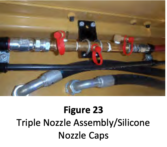
Ensure all discharge hoses are connected and nozzle caps are in place prior to discharge of system.
-
ROP & LOP Systems are discharged using the a manual actuator Cartridges that have been measured as underweight can be used for manual actuating the ROP system. Systems that are fitted with FLD linear detection must be discharged via the electric circuity to ensure that the discharge solenoid operates correctly
-
Check that all nozzle dust caps have blown off and that all nozzles are discharging F3 solution correctly
-
If nozzles caps do not dislodge correctly or coverage is inadequate, nozzles or discharge hose assemblies may be blocked. In this case Procedure 10.3 will need to be carried out. After this flushing prouder is completed the system will need to be recharged and discharged again to confirm accurate discharge time and coverage.
-
Confirm that all fire risk areas are adequately protected by F3 foam
-
Record the effective discharge time in seconds
-
All actuation and discharge hoses must be flushed with compressed air or nitrogen to ensure any residual solution is removed from hoses
-
Refill and recharge the FSI Foam Guard Fire Suppression system as per procedure 15 or 16
-
Reset display panel to normal operational condition
DISCHARGE HOSES – SYSTEM FLUSHING REQUIREMENT
-
Remove discharge hose(s) from the cylinder valve(s).
-
Plug remaining discharge hose on multi cylinder configurations.
-
Connect the FSI ROP and LOP Discharge Circuit Flushing Tool to a compressed air or nitrogen supply and then connect the FSI ROP Flushing Tool to the discharge hose as per figure 50.
-
Flush the discharge hoses of all residual solution. On larger systems separate sections may need to be flushed individually.
-
Disconnect the FSI ROP and LOP Discharge Circuit Flushing Tool from the discharge hose end.
-
Reattach the discharge hose end to the cylinder valve discharge nipple.
-
Reattach ALL silicone nozzle dust caps.
ACTUATION HOSES – LOP SYSTEM FLUSHING REQUIREMENT
-
The Fire suppression system must be isolated or depressurised prior to commencing any testing or maintenance to the actuation circuit to prevent the uncontrolled discharge of F3. To avoid personal injury, ensure all disconnected actuation hose assemblies are adequately secured with suitable p clamps or cable ties for this procedure.
-
Disconnect the 1/4” JIC actuation hose assemblies at the cylinder discharge valve(s) and LOP detection tube connection points. Manual actuators will require the safety pin to be removed and the release valve lever turned anticlockwise 90°.
-
Connect the FSI ROP and LOP Actuation Circuit Nitrogen Leak Tester and Flushing Tool to the nitrogen supply
-
Flush the actuation circuit with nitrogen to ensure all contaminants are removed from the internals of the hose and hose fittings and ensure there are no restrictions.
-
Remove actuator cover and refit pressure relief port silicon cap.
-
Reconnect 1/4’’ JIC fittings sealing threads with LOCTITE 577.
-
After system has been pressurised carry out actuation line leakage test as per procedure 14.4.
CYLINDERS
-
THE CYLINDER MUST BE CONDEMNED (IF IT CANNOT BE DETERMINED THAT THE DAMAGE IS WITHIN THESE LIMITS THE CYLINDER MUST BE CONDEMNED)
-
Visually inspect cylinders for physical damage and ensure that cylinders will not exceed the 5-year period for hydrostatic pressure testing prior to next scheduled service.
-
Inspect both the front & rear surfaces of the cylinder for abrasion or damage.
-
If damage is identified compare the problem area with the limits given in Procedure 18.0 AS2337.1-2004 CYLINDER INSPECTION IF THE CYLINDER IS OUTSIDE THE LIMITS AS OUTLINED IN AS 2337.1
-
Replace cylinders NOT within the acceptable limits provided in AS2337.1-2004
-
Ensure the cylinder labels are attached and legible. Replace labels if damaged, missing or illegible.
CYLINDER BRACKETS
-
-
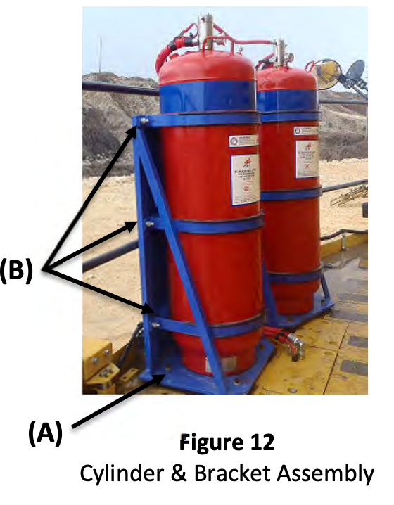
Ensure the cylinder bracket is free from damage and is securely mounted to the vehicle with M12 bolts, washers and nuts (A).
-
Ensure the cylinder is secured in the bracket and that there is no damage to the cylinder bands or rubbers.
-
If cylinder bands/rubbers are loose, remove bands and check condition of cylinder and band rubbers, replace if damaged. Refit bands and rubbers correctly ensuring that the cylinders are firmly secure (B).
-
Check and retention all band and bracket mounting bolts (A) & (B). Refer Figure 12.
DISPLAY PANEL
-
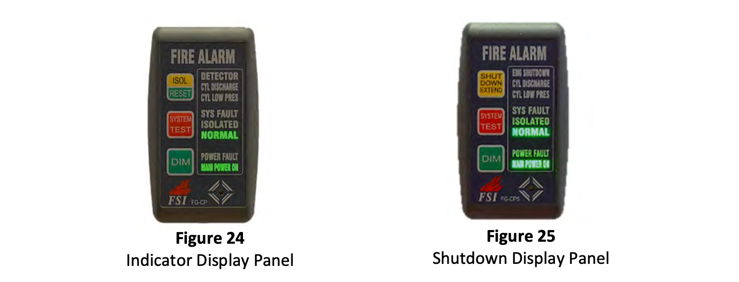
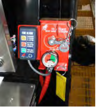
Ensure that the Display Panel is within the operator’s normal field of view and reach.
-
Ensure the Display Panel is well secured and in operational condition. Refer Figure 24 and figure 25
-
Test the operation of the Display Panel by depressing the System Test button. As per procedure 13.1.11 Indicator panel or procedure 13.2.6 Shutdown panel
-
Check all visual and audible alarms.
-
Replace LOP Decection Tubing
-
1. Locate all LOP deletion tubing 2. Confirm LOP Detection tubing locations are protecting the risk areas 3. Replace all LOP detection tubing and compression fittings 4. Replace all sheathers P clamps at required spacing using the correct sheathed p clamps. 5. Inspect the 1/4" Actuation Hose. Ensure that it is correctly secured to the LOP detection tubing 6. Pressurise detection circuit and carry out full actuation line leak test
CYLINDER DISCHARGE VALVE
-
WARNING: The cylinder is a pressure vessel. Do not remove any parts from the cylinder prior to depressurising the cylinder. Disassembly of cylinder discharge valves should be performed in a clean environment to minimise the possibility of contaminants. Always release cylinder pressure prior to removal of cylinder assembly parts.
-
Ensure that all items fitted to discharge valve are in good condition, correctly orientated, operational and that all hosing and wiring is secured and connected correctly.
-
If required, the cylinder discharge valve can be reconditioned/repaired.
LOP SYSTEMS - MANUAL ACTUATOR(S)
-
WARNING: Do not loosen any hose connections or fittings in the LOP actuation system while the system is
pressurised. This will cause the system to discharge. Prior to servicing any LOP actuators ensure the system is
depressurised by depressurising the PEFS F3 cylinders using the Schrader valve fitted to the cylinder Filler Plug
Assembly. Ensure pressure indicators on manual actuator reads zero pressure. -
Locate ALL Manual Actuators i.e. operator cabin, access stairs, paths of egress, E-Stops, service arms etc.<br>Cab Manual Actuator should be within the operator’s normal field of view and reach.
-
Inspect all Manual Actuators for visible signs of damage.
-
Replace damaged components as required. To replace any Manual Actuator, the system will need to be depressurised and recharged after this item replacement has<br>been completed.
-
Check that the securitie & pull-pin are in place on ALL Manual Actuators.
-
If the securitie or pull-pin is NOT in place check the system pressure to ensure that the system has not been actuated.
-
Check that the pressure indicator gauge is liquid filled and that the rubber grommet is in place.
-
Compare all Manual Actuator pressure indicator gauges to confirm that they are all indicating the same pressure and that all pressure indicators are in the green zone.
-
All safety-pins are to be removed and reinserted to ensure they are not damaged and are easily removable. Care must be taken to ensure that the system is not<br>inadvertently actuated whilst the safety pin is removed.
-
If the system HAS been actuated, check ALL Manual Actuators.
Refilling with Solution
-
1. Select the correctly sized FSI fill tube for the cylinder being refilled<br>2. Screw the correct FSI fill tube onto the cylinder neck ensuring it is seated and firmly hand tight<br>3. Fill with potable water using a hose or container until water is sitting at the top of the fill tube<br>4. Remove fill tube 5. Accurately measure out the correct amount of F3 concentrate as stated on the cylinder label or manual 6. Using a funnel pour slowly into cylinder 7. Ensure the O-ring at the top of the syphon tube is in good condition and there is molykote 111 on the bevelled lip of the cylinder neck 8. Carefully reinstall the valve and hand tighten only. 9. Carry out same procedure for multiple cylinders
NOZZLES / SILICONE NOZZLE CAPS
-
-
Remove nozzle caps and clean ALL nozzle outlets using a damp clean cloth. Visually inspect to ensure that ALL nozzle orifices are free from contaminants or foreign materials.
-
Inspect silicone nozzle caps. Refit dislodged caps and replace if missing or damaged.
-
Ensure the direction of the spray outlet of each nozzle is unobstructed and that there are no obstructions between the nozzle and the hazard likely to restrict the discharge of the foam solution.
-
Ensure that each nozzle is aligned correctly i.e. directed toward the hazard it is protecting.
-
Ensure that all nozzle assemblies are firmly secured and that all hose assemblies are correctly connected to the nozzle assembly.
System Pressurising
-
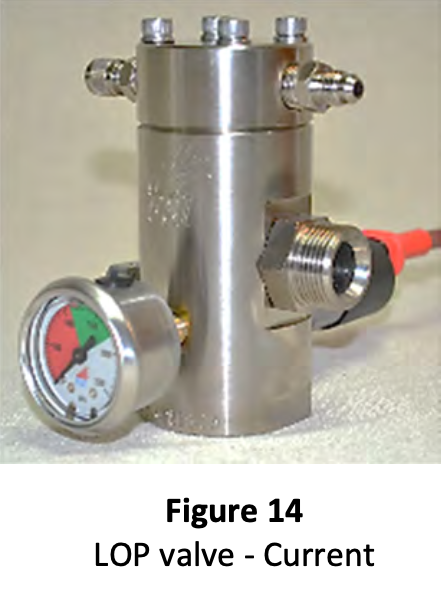
LOP systems are pressurised using the Schrader valve fitted on top of the LOP Valve Assembly or using the Schrader valve fitted on the manual LOP actuators.
WARNING: Do not pressurise a cylinder that is not in test date. -
The control panel MUST BE ISOLATED AND RESET prior to recharging the fire suppression cylinders. Disconnecting any power supply WILL NOT reset the latching switch which controls the electric actuation solenoid valve.
-
NOTE: Do not pressurise LOP systems using the schrader valve on the filler port assembly of the PEFS cylinders.<br>This will cause the cylinder to discharge.<br>1. Ensure the actuation hose is fitted and sealed with Lactate 577 to top of the valve<br>2. Cap the discharge port of each cylinder valve to prevent solution loss in the event of an accidental discharge.<br>3. Remove Schrader valve cap from upper and lower Schrader valve<br>4. Connect the Charging rig to nitrogen regulator, and set the nitrogen regulator to a pressure of 2200kPa<br>5. Connect both charging hoses to upper an lower Schrader valves<br>6. Open charging ball valve monitor cylinder gauge until pressure reaches 1700kPa<br>7. Allow a minimum of 5 minutes for cylinder pressure to stabilize before disconnecting charge rig. Depending on ambient temperature cylinder pressure will settle back to between 1600kPa and 1650kPA<br>8. Disconnect both charging hoses from upper and lower Schrader valves<br>9. Check all connections at valve assembly for leaks using leak detection fluid. If a leak is present system must be depressurised and problem fixed<br>10. Re-fit the upper and lower Schrader valve caps<br>11. Disconnect cylinder isolation cap from the discharge outlet on the valve and reconnect discharge hose 12. Reset fire alarm display panel to its normal operation condition. As per procured 13.1.12 or 13.3.8
After Maintenance Activities
-
After all Yearly maintenance activities have been completed:
-
1. Ensure all pressure indicators are reading in the green zone.
-
2. Ensure all labels are in good condition (refer 6 monthly service item 8)
-
3. Ensure control panel (where fitted) is reset to its normal operation mode and is no longer in its “Isolation / Test” mode.
-
4. Ensure panel status lights are in normal condition (refer 6 monthly service item 2)
-
5. Complete routine service records in accordance with AS5062
-
6. Stamp Service Tag with the number “2” in the corresponding Year/Month location.
Further repairs required:
-
Comment:
Labour time:
-
Labour
Sign Off
-
I Hear by certify that the above system has been in accordance with AS5062 and the information on this service record is true and correct
From PIRTEK
-
Pirtek Centre Name:
-
Technician Name:
- Ashley Lawson
- Chris Paton
- Peter Eversham
- Tim Eversham
- Nick Stallard
- Coedy Kleinig
-
Cert Number: QTEC L1083
-
Email: Ashley@pirtekeme.com.au
-
Position: Service Technician
-
Cert No: L1084
-
Email: Chris@pirtekeme.com.au
-
Position: Service Technician
-
Cert No: E-086
-
Email: Peversham@pirtek.com.au
-
Position: Service Technician
-
Cert No: E-0146
-
Email: Teversham@pirtek.com.au
-
Position: Service Technician
-
Cert No: L0963
-
Email: Nick@pirtekeme.com.au
-
Position: Service Technician
-
Cert No: L0958
-
Email: Coedy@pirtekeme.com.au
-
Position: Service Technician
-
Signature:
From Customer/End User
-
Name
-
Signature:


