


Information
-
Audit Title
-
Document No.
-
Client / Site
-
Conducted on
-
Prepared by
-
Location
-
Personnel
Commissioning Report
At the time of the initial diagnostic service mobilization, the Technician will note any deficiencies in the existing system regarding compliance with UL325 standards and advise the customer of same. Systems that do not comply with current UL325 standards may or may not be serviced at this time at our discretion. Technician will also determine at that time if the requested work is covered under warranty, at which point some or all of the charges may be waived.
PERFORMANCE VERIFICATION TESTS
-
Below is a list of Required Items that will be needed to complete the PVT.
1) Safety vest
2) Stop watch
3) Verify Contractor will have at least four (4) radios/walkie-talkies.
4) Verify Contractor will have flag-persons if ACP (Access Control Point) is not being closed.
5) Pad of paper and pen or pencil
6) If still active construction site, verify a hard hat is required.
7) If still active construction site, verify steel toed boots will be required.
8) Copy of any pertinent drawings and/or specifications
9) Vehicle or four pieces of sheet metal (minimum size equivalent to a laptop computer) for AVB
(Active Vehicle Barrier) Safety Loop Detector Testing.
10) Measuring Wheel -
ATTENDANCE ROSTER
-
Add signature
-
Add signature
-
Add signature
-
Add signature
-
Add signature
-
Add signature
-
Add signature
-
Add signature
-
Add signature
-
Add signature
-
Access control point designation
-
Testing conditions (Weather, Temperature, etc)
-
Serial number
-
Is the Power Unit Cabinet protected from vehicle impact?
-
AVB Drainage type
-
Type of Controller
-
Location of Controller
-
Is there a generator on site?
AVB TEST MASTER CONTROL PANEL
-
Keyed two-position switch labeled “MASTER POWER” with “ON” and “OFF” key positions.<br>Verify that power at all panels is off and that no switches and push buttons operate
-
Ensure Master Control Power Switch is turned to the ON position and the red indicating light<br>is illuminated
-
Verify the Raise LED activates on all panels
-
Verify the Raise LED turned off and the Lower LED turned on at all panels
-
Verify that REMOTE PANEL(S) do not operate in the off position
-
Verify the EFO active light turns on at all panels
-
Verify that the Barrier Raise LEDs activate for all lanes at all panels
-
Verify that the Barrier Lower LEDs turn off for all lanes at all panels
-
Verify that the normal Lower Buttons are inactive at all panels
-
Activate the EFO Reset, Verify the EFO Active light turns off
-
Verify the Raise LED turned off and the Lower LED turned on at all panels
AVB TEST REMOTE CONTROL PANEL(S)
-
Repeat 11.04 in its entirety for each remote panel on the system.
Note: Test Remote Panels one at a time. -
From the Master Control Panel turn on the Remote Control Panel
-
Verify that the Remote Control Panel LED is illuminated when the panel is on
-
Verify the Raise LED activates on all panels
-
Verify the Raise LED turned off and the Lower LED turned on at all panels
-
Verify the EFO Active light turns on at all panels
-
Verify that the Barrier Raise LEDs activate for all lanes at all panels
-
Verify that the Barrier Lower LEDs turn off for all lanes at all panels
-
Verify that the normal Lower Buttons are inactive at all panels
-
From the Master Control Panel, activate the EFO Reset
-
Verify the EFO Active light turns off
OPTIONAL SAFETY LOOP TESTING
-
Repeat Loop testing in its entirety for every loop in the system independently.
-
If the system is equipped with Safety loops, activate a Safety Loop Detector by placing a vehicle or metal plate over the loop.
-
Activate the Raise Button verify the barrier does not raise
-
Activate the Lower Button verify the barrier does not raise
-
Active the EFO Pushbutton. Record time to fully deploy in seconds
-
Note: Depending on the specification of the individual site the EFO may still operate or may not
operate. If the specification calls for the EFO to not operate Stop here, otherwise continue. -
Verify the EFO Active light turns on at all panels
-
Verify that the Barrier Raise LEDs activate for all lanes at all panels
-
Verify that the Barrier Lower LEDs turn off for all lanes at all panels
-
Verify that the normal Lower Buttons are inactive at all panels
-
Activate the EFO Reset
-
Verify the EFO Active light turns off
-
Verify the Raise LED turned off and the Lower LED turned on at all panels
-
MAINTENANCE DATA SHEETS AND RECORDS
-
Has customer been made aware of the Hercules High Security Preventative Maintenance Agreement
-
12.03 MAINTENANCE DATA SHEETS AND RECORDS
The Owner/Operator is responsible for keeping maintenance and service records during the
warranty period of the equipment and shall submit records to Ameristar or their Authorized
Service Representative for review, upon request, or when making a warranty claim. In addition,
any failed, malfunctioning, excessively worn, or damaged parts must be returned to Ameristar or
their Authorized Service Representative upon request, for inspection when making a warranty
claim.
12.04 TOOLS AND SUPPORT EQUIPMENT
The Barrier System requires minimal maintenance activities. The equipment can be maintained
using a standard mechanics tool set and a few support equipment items.
12.04.1 Standard Tools
Standard tools are recommended as follows:
1) Mechanics hand tools.
2) Standard power tools.
3) Allen wrench socket set.
4) Torque wrench.
5) Crows-feet set for socket wrench.
6) Drip pans and leakage catch basins.
7) Waste fluid containers.
8) Wet/dry vacuum (suitable for collecting hydraulic fluid spills)
12.04.2 Support Equipment
Support equipment items are recommended as follows:
1) Nitrogen Bottle High Pressure Regulator — a high pressure regulator which allows
controlling pressure from a nitrogen gas cylinder during Accumulator gas pre-charging.
2) Accumulator Gas Pre-Charge Kit — a kit which allows connection of the Accumulator
to a high pressure nitrogen gas cylinder regulator during Accumulator gas pre-charging.
This kit should include a special Accumulator “T” valve adapter, pressure gauge and
hose.
3) Hydraulic Fluid Transfer Pump and Filter — a portable transfer pump and filter unit
which allows filling of the HPU Reservoir with pre-filtered hydraulic fluid, out of standard
55 gallon (208 liter) drums.
4) Dead-Blow Hammer — to fix stubborn components, or at least teach them a good
lesson for messing up.
5) Thermometer — a thermometer which has an appropriate range to measure the
ambient air temperature during Accumulator gas pre-charging, or checking the hydraulic
fluid temperature during troubleshooting.
6) Stop Watch — a stop watch which allows checking Barrier speed during adjustments.
7) Digital Multi-Meter — a hand-held, digital multi-meter (with test leads) which allows
checking of electrical voltage, current, switch contact state and resistance during
troubleshooting.
8) Test Jumper Leads — an electrical test jumper lead with alligator clips on both ends for
simulating switch closures or forcing signals during troubleshooting.
Support equipment items are not supplied with the Barrier System, but may be ordered
separately from Ameristar. Contact Ameristar for additional information on these support
equipment items.
Page 65 of 125
Titan Operation and
Maintenance Manual Ameristar Perimeter Security USA Inc. Rev. 12/2/2019
12.04.3 Overhaul Tools
Overhaul tools would only be required for an overhaul of equipment, or major repair.
Overhaul tools are recommended as follows:
1) Spanner wrench (for disassembly of an accumulator).
2) Hose cut-off saw and hose crimper.
3) Solvent parts washer (for cleaning hydraulic components).
12.05 SERVICE SUPPLIES
The following service supplies will be required for Barrier System operation:
1) Dry gaseous nitrogen — per MIL-P-27401, or technical nitrogen per BB-N-411. High
pressure compressed gas cylinder, 2265 PSIG, DOT specification 3AA2265, with shutoff
valve, used for pre-charging the Accumulator.
2) Hydraulic fluid, used for filling the HPU Reservoir
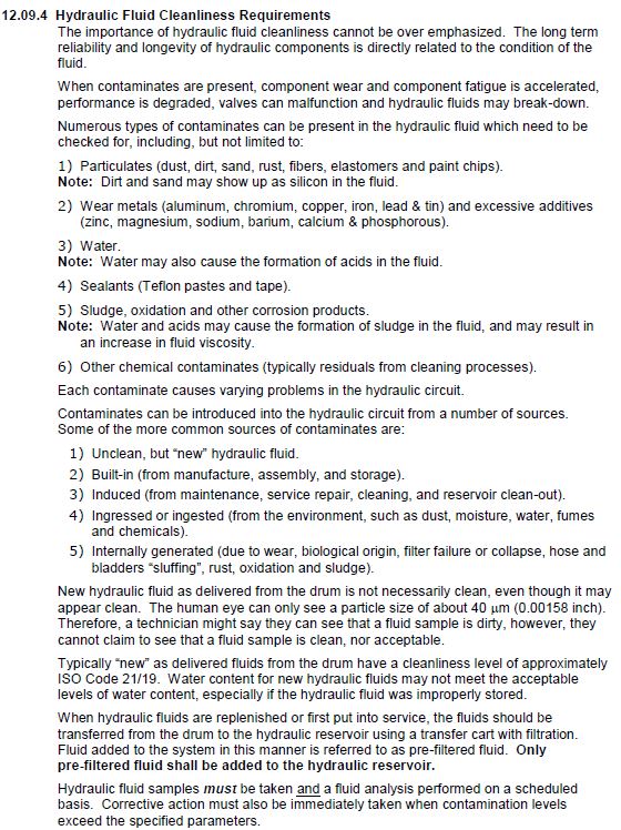
Note: All hydraulic fluid must be pre-filtered to ISO Code 17/14 or better prior to use.
Refer to the HYDRAULIC FLUID PROPERTIES section 11.5. for additional information.
CAUTION: Do not mix hydraulic fluid types, as damage to the hydraulic circuit and
components may occur.
3) Lubrication grease — used for lubricating pivot points, linkages, and wear bearings. Use
Mobil CM-P extreme pressure grease, or equivalent.
4) Hydraulic fluid (oil) absorbent materials — for both containing and cleaning up hydraulic
fluid spills and/or leakage.
5) Lint-free wipes — for use around hydraulic components, lines and fittings.
Service supplies are not supplied with the Barrier System, but may be ordered separately from
Ameristar. Contact Ameristar for additional information on these supplies.
12.06 SPARE PARTS
Spare parts are not supplied with the Barrier System, but may be ordered separately from
Ameristar. The extent of the Spare Parts recommended is dependent on the security
requirements of the site, the amount of acceptable time a Barrier System can be down, and the
capabilities of on-site or locally available service support. Contact Ameristar for specific site
recommendations and additional information on spare parts.
In addition to replacement spare parts, Ameristar recommends that each site stock standard
consumable items such as indicator lamp bulbs, filter elements, fuses, etc., which may be
needed for normal long-term operation. Consumable items and the replacement of these items
are not covered by the Barrier System Warranty.
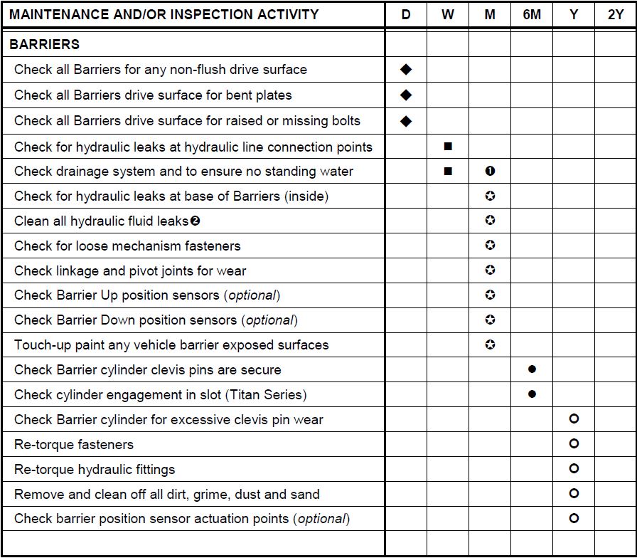
12.07 MAINTENANCE AND INSPECTION INTERVALS
Maintenance and inspection intervals have been established based on typical Barrier System
usage. These intervals may need to be shortened for sites where the Barrier System is
subjected to severe environment, harsh duty cycles, and/or frequent operation. The inspection
and maintenance procedures must be performed regularly and thoroughly according to the
indicated schedule to prevent equipment damage, minimize failure, and to keep the Barrier
System operational.
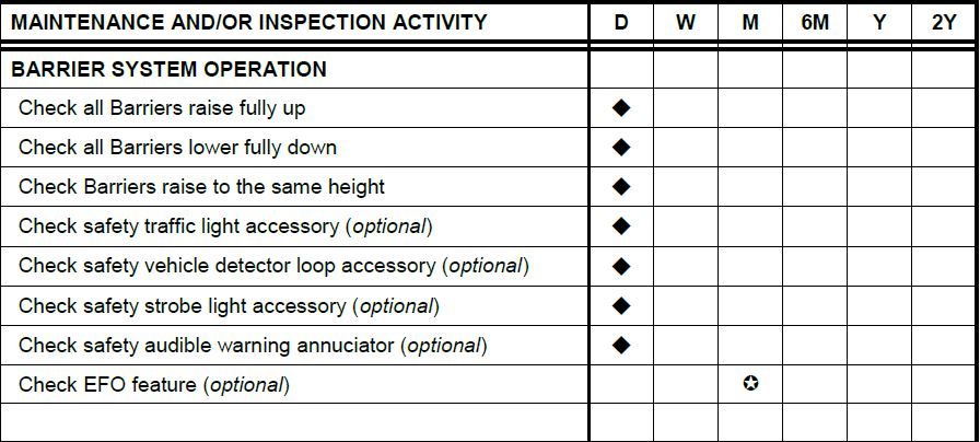
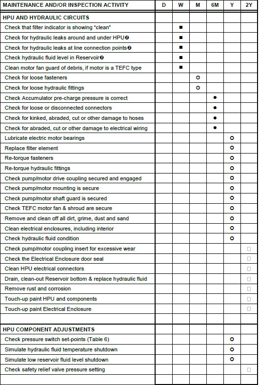
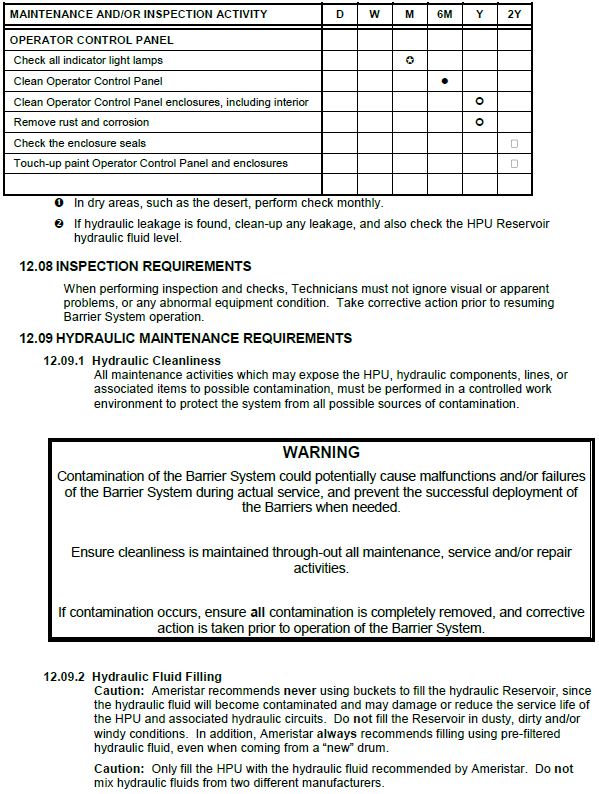
The Barrier System periodic maintenance and inspection intervals are shown in Table 6. During
inspection and maintenance activities, any abnormal wear, damage, failures and/or defects
discovered during these activities must be corrected before returning the Barrier System to
operation. -
-
-
-
-
-
-
-
-
-
-
-
-
-
Technician’s Recommendations
-
Comments
Electronic Signature Acknowledgement-I agree that my Electronic signature is a Legally and Binding Equivalent to my handwritten signature. Whenever I execute an Electronic Signature, it has the same validity and meaning as my Handwritten Signature. I will not at ANY time in the future, REPUDIATE the meaning of my Electronic Signature or Claim that my Electronic Signature is not Legally Binding.
-
Hercules High Security Representative
-
Customer representative’s signature


