Title Page
-
Site Name
-
Conducted on
-
Prepared by
-
Location
-
Start time
-
Employees
- Raul Reyes
- Nate Rollison
- David Bonilla
- Nick Nichols
- Mark White
Necessary NMSB VI–H Bollard Information
-
Technical support- 800-395-9597
-
Email- HHS@HerculesFence.com
-
Mandatory start images
-
Inspect and Clean the Mechanical System
Mechanical Operation Preventative Maintenance and Inspection (PM&I) applies to all NMSB VI-H
bollards. The mechanical system on the NMSB VI-H should be inspected every 100 hours of
operation or monthly, whichever is sooner. When inspecting the barrier be sure that unauthorized
personnel and vehicles are clear of the barrier. With the barrier in the secure position inspect and maintain. A. Ensure the Bollard Assembly is not interfering with anything that could inhibit the barrier from
operating.
B. Verify that the Bollard Assembly glides smoothly inside the Housing Assembly. If the Bollard
Assembly is not aligned correctly, it will bind and effect the operation of the barrier. Contact
Nasatka if the barrier is not properly aligned.
C. Housing Assembly
Keeping the inside of the housing clean and free from debris is important so the barrier can
function properly. The following are steps to guide you with this process:
De-energize the power to the barrier before doing anything inside the housing.
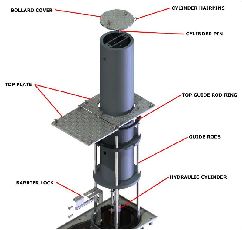
Remove the top plate and remove any debris including sticks, stones, leaves, etc. from
around the bollard assembly (see Figure 22 and Figure 23). Please note when reinstalling
top plate screws it is recommended that anti seize be applied to the screws. -
Clean the inside of the Bollard Housing
-
Inner Post Removal
If more cleaning is required, remove the inner tube. Removing the inner post is not normally
performed and will require equipment capable of lifting approximately 600 lbs. It is
recommended that service be scheduled prior to attempting this action.
The removal of the inner post should only be necessary if debris such as sand and stones have
permanently wedged themselves between the guides of the inner post and the wall of the
housing.
Loosen and remove cover screws from top plate and bollard cover; remove top plate and
bollard cover.
Using proper lifting equipment, rig and support weight of inner tube (600 lbs).
Remove barrier stop and barrier lock.
Lift inner post to the near fully extend position.
Remove cylinder hair pins and cylinder pin.
Lift inner tube out of housing
Clean and or remove embedded debris from inner post slides
Inspect wall of housing
Install inner post, reversing removal sequence. -
Are ALL of the access plate, T-45 Torx head screws in acceptable condition
-
Guide Rods<br>The guide rods guide the bollard vertically during secure and nonsecure functions. It<br>is important for the rods to be regularly greased in order to maintain smooth and quick movement of<br>the bollard. It is the recommendation of Nasatka to remove the top plate and apply a few drops of<br>white lithium grease on the guide rods every 2-4 months. Has White lithium grease been added to the guide rods on this Preventative Maintenance trip?
-
Date of service
-
-
Checking the Hydraulic System
WARNING
Prior to doing any hydraulic repairs; arrange the barrier in nonsecured position and
release all hydraulic pressure by opening accumulator valve. Pressure gauge should
read zero once all pressure in the system has been released.
One of the key factors for good service and long life from a hydraulic system is cleanliness. The
NMSB VI-H requires 100 hour or monthly PM&I activities. It has been our experience that most dirt
infiltrates a hydraulic system during installation or while servicing the system components, so we
recommend the following: -
All interconnecting tubing, pipe, and hoses should be cleaned so they are free from rust and dirt
-
Reason for failure
-
Current condition
-
Bollard Cylinder
-
Inspect the hydraulic cylinder and cylinder connections for hydraulic fluid leaks
-
Reason for failure
-
Current condition
-
If threaded connections are leaking, tighten loose connections
-
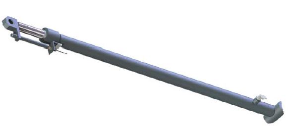
If seals are leaking on cylinder, replace cylinder.
-
Reason for failure
-
-
Are the actuator and spring assembly rod-eyes tight and free of excessive wear
-
Are the split journal bearing bolts tight and free of excessive wear
-
Has the excess dirt and debris been cleared from the Bollards and vault
-
Is the servo drive panel or connectors free from damage
-
Is the field wiring and cables connected per system interconnect drawings (From junction box to BCP)
-
Is the Ethernet termination on the servo drive free of corrosion
-
Has the correct power been supplied from the RSSI automatic transfer switch CB1 (240VAC or 208VAC between L1 & L2)
-
Are you receiving 120VAC between L1 & Neutral (2)
-
Are you receiving 24-27 VDC at the battery cables to the inverter
-
Are there any parts that need to be replaced
-
Parts needed
-
Mandatory finish images
Electronic signature acknowledgement- I agree that my signature is a legally and binding equivalent to my handwritten signature. Whenever I execute an electronic signature, it has the same validity as my handwritten signature. I will not at any time in the future, repudiate the meaning of my electronic signature or claim that my electronic signature is not legally binding.
-
Hercules High Security Representative
-
Customer
-
Completion time


