


Title Page
-
Site Name
-
Model number
-
Serial number
-
Voltage
-
Cycle count
-
Conducted on
-
Prepared by
-
Location
-
Start time
-
Employees
- Raul Reyes
- Nate Rollison
- David Bonilla
- Nick Nichols
- Mark White
Necessary RSS4000 Information
-
Mandatory start images
-
Technical support- 850-871-9300
-
Email- Service@rssi.com
-
BARRIER MAINTENANCE
Maintenance of the RSS-4000 barrier consists of routine Preventative Maintenance Procedures, which
RSSI recommends quarterly or semi-annually and non-routine maintenance procedures. Preventative
Maintenance Procedures can be found on page 22, Attachment 4. Non-routine Maintenance Procedures
are addressed in this section. -
Tools needed: 1. Cordless impact wrench or ratchet wrench with TORX 45 bit 2. Cordless drill with adapter for 15/16 socket 3. Flashlight and gloves BEFORE YOU INITIATE MAINTENANCE OPERATIONS All Maintenance Operations must be coordinated with site personnel
BARRIER MAINTENANCE<br>Maintenance of the RSS-4000 barrier consists of routine Preventative Maintenance Procedures, which<br>RSSI recommends quarterly or semi-annually and non-routine maintenance procedures. Preventative<br>Maintenance Procedures can be found on page 22, Attachment 4. Non-routine Maintenance Procedures<br>are addressed in this section.
-
WARNING
● Place traffic cones and block roadway from traffic to ensure worker safety
● Use the proper tools when required to help avoid serious personal injury and
damage to components.
● Never operate this equipment when a vehicle, person or any obstruction is in the
way of full operation of the RSS-4000. -
16 Attachments
1. Barrier Control From Maintenance Touch Screen
2. Initiate Advanced Maintenance Operations (From Maintenance Touch Screen in BCP)
3. Removing Barrier Insert from Vault
4. Preventative Maintenance Checklist
5. Replace Actuator
6. Replace Sump Pump
7. A. Replace Feig Loop Sensor
B. Replace EMX Loop Sensor
8. Replace Spring
9. Replace Servo Drive Fuse
10. Replace LED Traffic Light
11. Replace Servo Drive Panel in Barrier
12. Replace Bollard LED Lights
13. A. Replace Surge Protection Module in BBP
B. Replace Voltage Monitor Module in BBP
14. Replace Surge Protection Module in BBP
15. Replace 24 VDC Power Supply in BCP
16. Replacing Touchscreens
ATTACHMENT 1- BARRIER CONTROL FROM MAINTENANCE TOUCH SCREEN
-
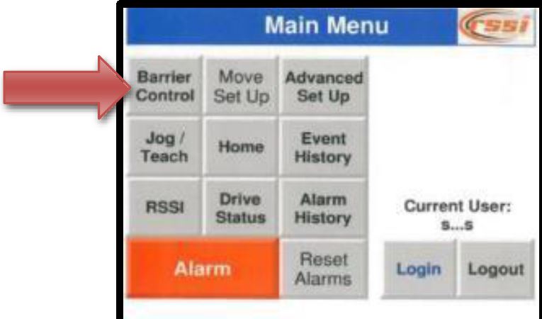
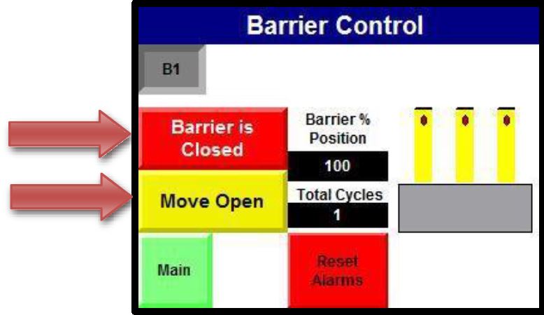
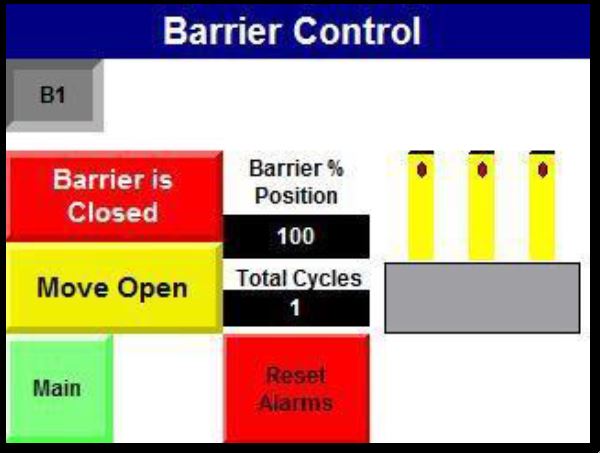
1. From the MAIN MENU, press the BARRIER CONTROL button
-
-
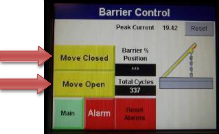
2. Inside the BARRIER CONTROL menu use the MOVE CLOSED/OPEN buttons to operate the barrier a few cycles, measure the post assembly in the CLOSED (UP) position to ensure it reaches 35-36 inches and ensure the OPEN(DOWN) position is all the way down and out of roadway
-
NOTE
If the Peak Current is higher than 20 Amp, it may indicate that the barrier
position needs to be adjusted. Refer to Step 5 in Attachment 2.
NOTE
If the barrier post assembly is not flush with the roadway (protruding from
barrier), -
FROM THE MAINTENANCE TOUCH SCREEN IN THE BCP
Homing the Barrier -
1. Turn on Fuse FU1. On the maintenance touch screen in the BCP, go to the main screen and check for any alarms and reset or clear
-
2. At the Main Screen, go to the LOGIN box and login: “RSSI” password: “32404”.
-
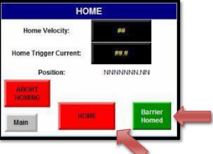
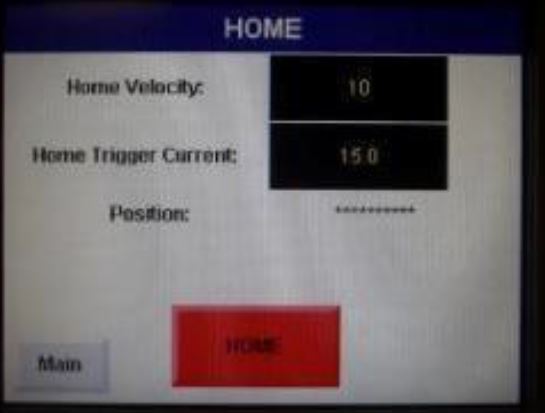
3. Once you have logged in at the Main screen, select the HOME box and then at the HOME menu press the red HOME button. The Home button will flash while homing, once it has completed the process the green BARRIER HOMED button will appear. The barrier is now homed, select Main to return to main screen
-
-
Barrier Control 1. From the MAIN MENU, press the BARRIER CONTROL button
-
-
2. Inside the BARRIER CONTROL menu use the MOVE CLOSED/OPEN buttons to<br>operate the barrier a few cycles, measure the post assembly in the CLOSED(up) position<br>to ensure it reaches 35-36 inches and ensure the OPEN(down) position is all the way<br>down and out of roadway
-
NOTE
If the Peak Current is higher than 20 Amp, it may indicate that the barrier
position needs to be adjusted.
NOTE
If the barrier post assembly is not flush with the roadway (protruding from
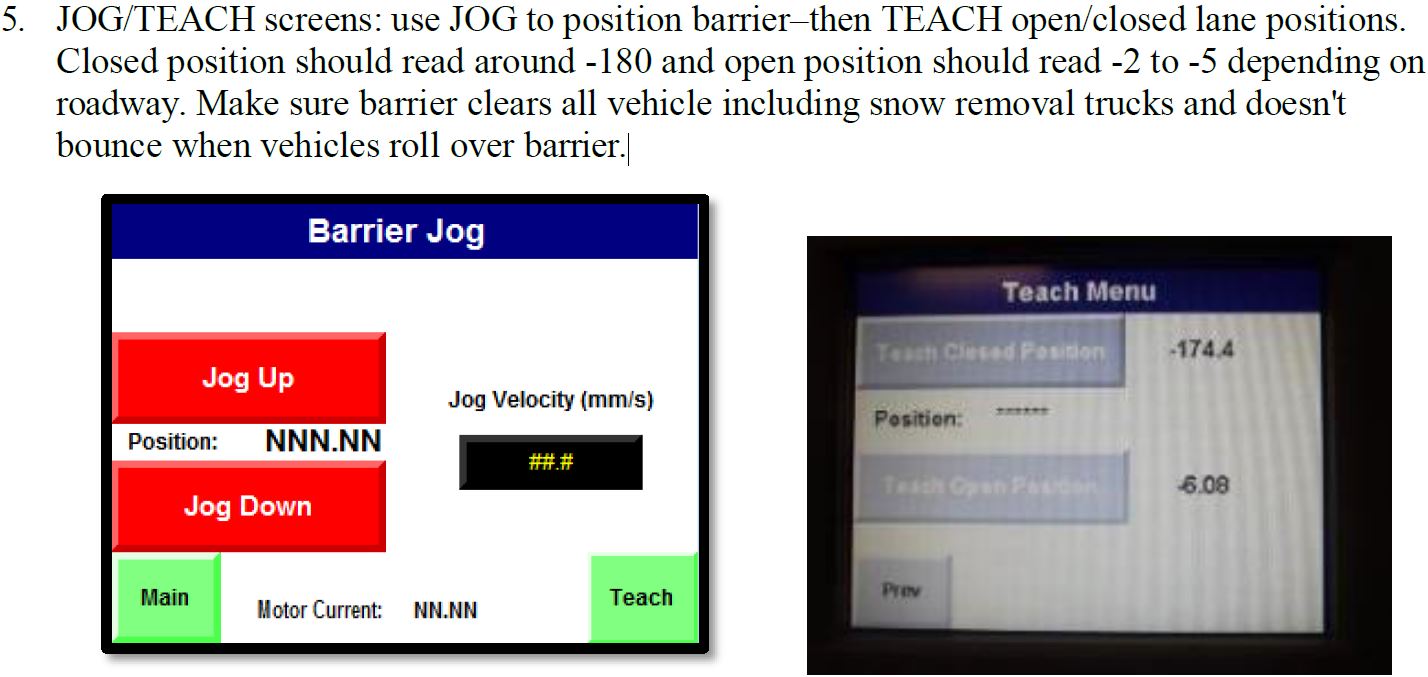
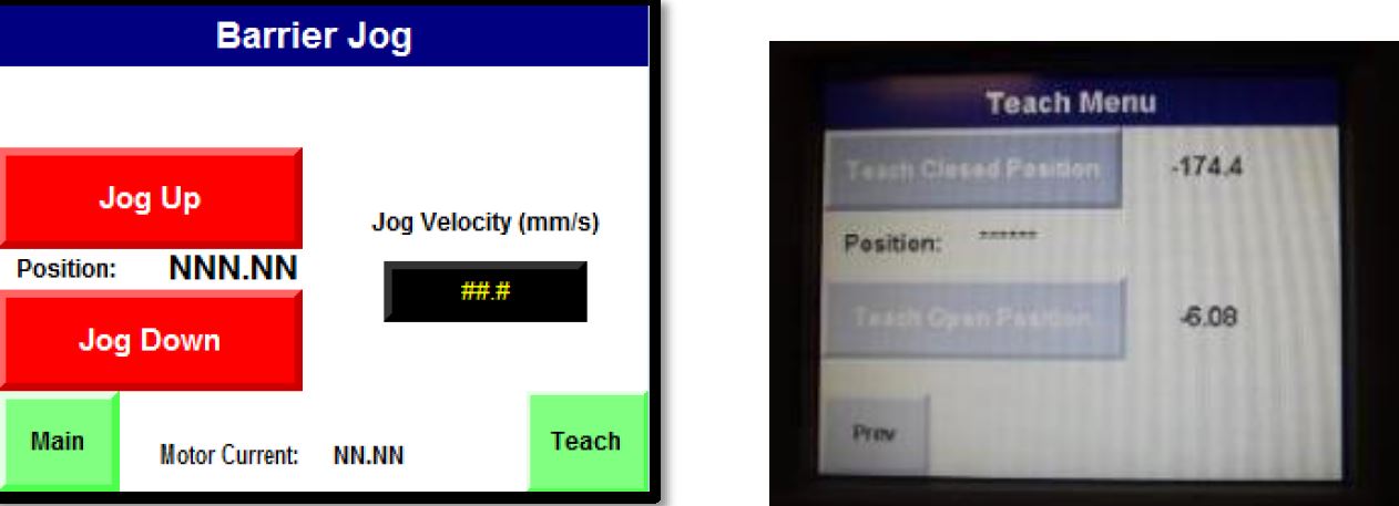
barrier) JOG/TEACH screens: use JOG to position barrier–then TEACH open/closed lane positions.
Closed position should read around -180 and open position should read -2 to -5 depending on
roadway. Make sure barrier clears all vehicle including snow removal trucks and doesn't
bounce when vehicles roll over barrier. -

ATTACHMENT 2 - INITIATE ADVANCED MAINTENANCE OPERATIONS (FROM MAINTENANCE TOUCH SCREEN IN BCP) The Maintenance Touchscreen located in the BCP (Barrier Control Panel).
-
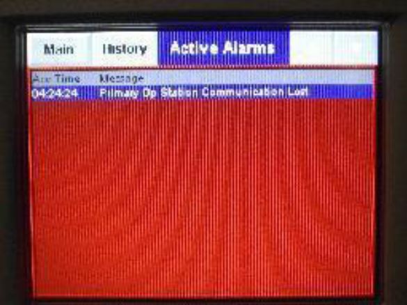
1. ALARM Screen: Clear Active alarms before proceeding).
-
-
2. LOGIN Screen User= RSSI, PW=32404
-
-
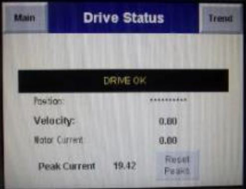
3. DRIVE STATUS screen: Drive Status must be DRIVE OK – if it is not resolve by checking trouble shooting table
-
-
4. HOME Screen: Technician can HOME barrier or abort HOMING, if barrier gets out of HOME again, the touchscreen will show message and direct technician to re-home. If barrier doesn't complete Homing in 30-45 seconds, verify Drive Status in Item 3 above. If Drive is OK, attempt to HOME again. If it doesn’t complete Homing a 2nd time, pressing the abort homing button will stop HOMING procedure. Contact RSSI for assistance.
-
-
5. JOG/TEACH screens: use JOG to position barrier–then TEACH open/closed lane positions. Closed position should read around -180 and open position should read -2 to -5 depending on roadway. Make sure barrier clears all vehicle including snow removal trucks and doesn't bounce when vehicles roll over barrier.
-
-
CAUTION
DO NOT change any other settings on this screen without FIRST contacting RSSI. Doing
so may change the operating characteristics of your barrier. -
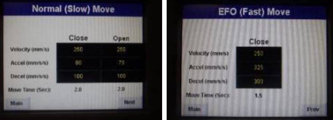
6. MOVE screen: using accel/decel to select speed of barrier EFO speed (use defaults)
-
7. Barrier Control Screen: run barrier through a series of open/close movements while monitoring the AMP indicator. Should be less than 15 amps close lane and less than 10 amps open lane. T/shoot high amp movements before proceeding. Recheck Manual Screw, must be Disengaged.
-
-
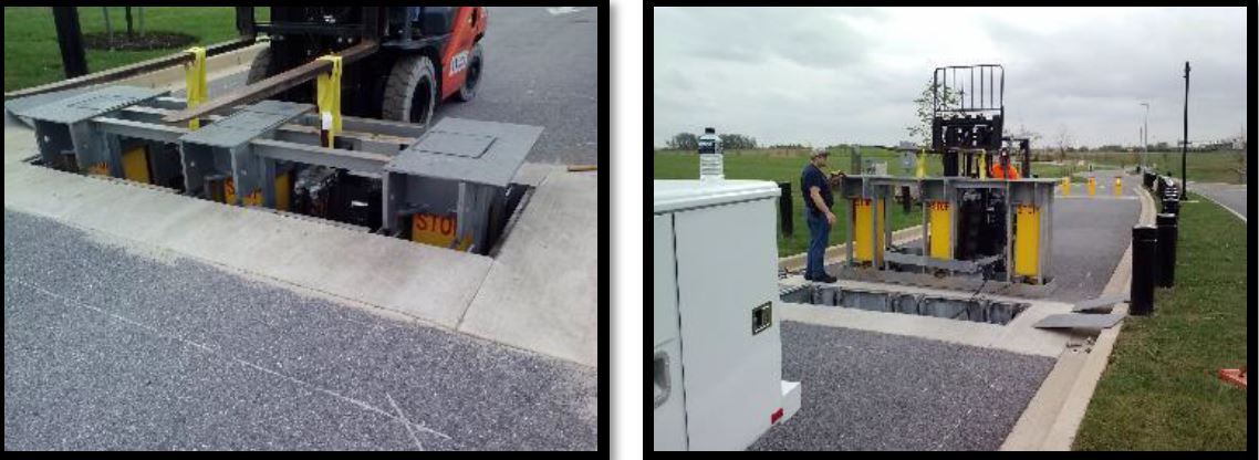
ATTACHMENT 3- REMOVING BARRIER INSERT FROM VAULT Tools needed: Always have these tools readily available 1. Cordless impact wrench or ratchet wrench with TORX 45 bit 2. Lifting Straps 3. Forklift BEFORE YOU INITIATE MAINTENANCE OPERATIONS All Maintenance Operations must be coordinated with site personnel.
-
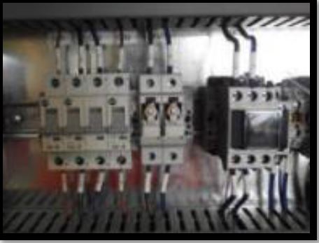
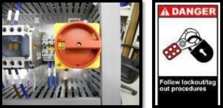
1. Disconnect power to the barrier by turning off the Main Disconnect and lock out with a wire tie or IAW local lockout procedures.
-
-
2. Disengage Servo Drive fuse
-
-
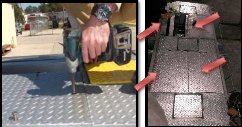
3. Remove top plate screws with TORX 45 bit, then remove top plates
-
4. Remove pins that secure insert to vault.
-
-
5. Attach Straps then align forklift to remove Insert. Secure all wiring while insert is being removed from vault. Place the insert securely next to the vault, do not damage wiring.
-


ATTACHMENT 4 - PREVENTATIVE MAINTENANCE CHECKLIST Make copies of this checklist for maintenance activity for each barrier and maintain a copy in the maintenance binder for the Warranty/Historical Record. For assistance, please call RSSI’s service department at (850) 871-9300 or email service@rssi.com.
-
Preventative Maintenance Steps 1. Turn power on to unit (if necessary) to check for proper voltage. 2. Place necessary traffic safety cones to ensure worker safety. 3. Check operation of unit by operating the barrier 3 times. Ensure that the post assembly rotates smoothly and reaches full UP and DOWN positions. 4. Check LED safety lights on barrier for proper operation. 5. Make sure the vehicle barrier is in the UP position and disconnect power to the barrier by turning off the Main Disconnect and lock out with a wire tie or IAW local lockout procedures.
-
6. Remove Access Plates. Using a cordless drill with a T-45 TORX Head Bit, remove the screws from the access plates. After all screws are removed move the access plate from the barrier.
-
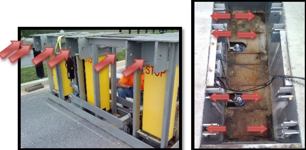
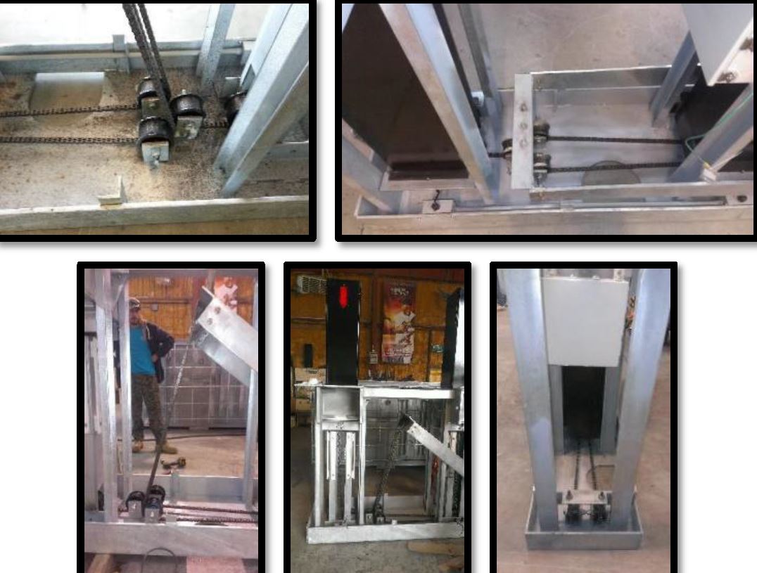
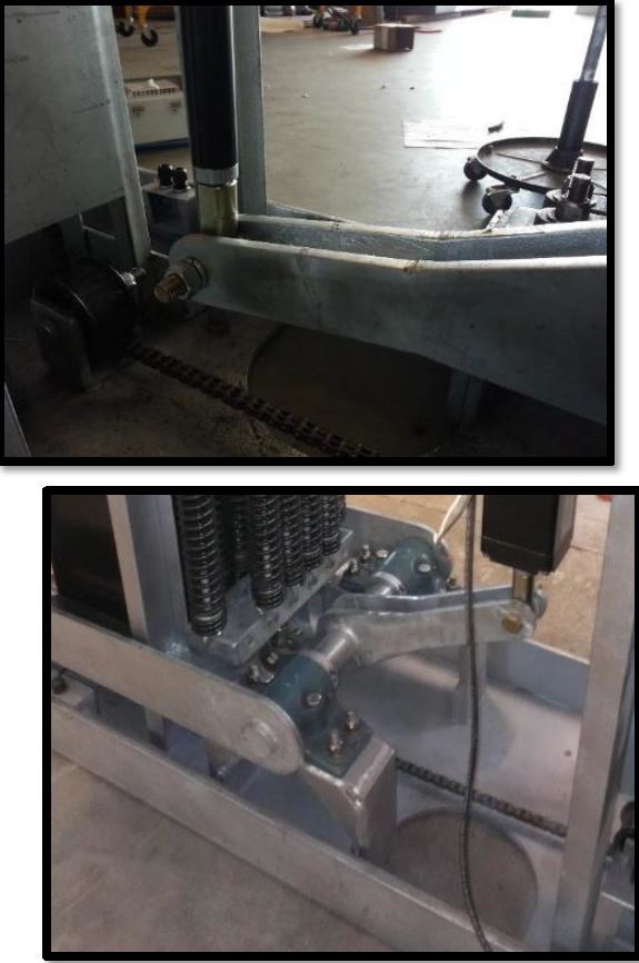
8. Check Actuator & Spring Assembly Clevis Brackets, Bolts, and Pins. If these connections<br>are not kept tight, it might cause loose motion that could result in excessive wear.
-
-
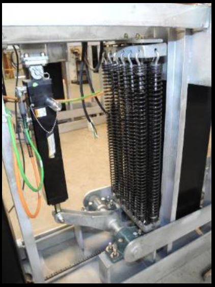
9. Check Chain and Pulleys for excessive wear or debris.
-
-
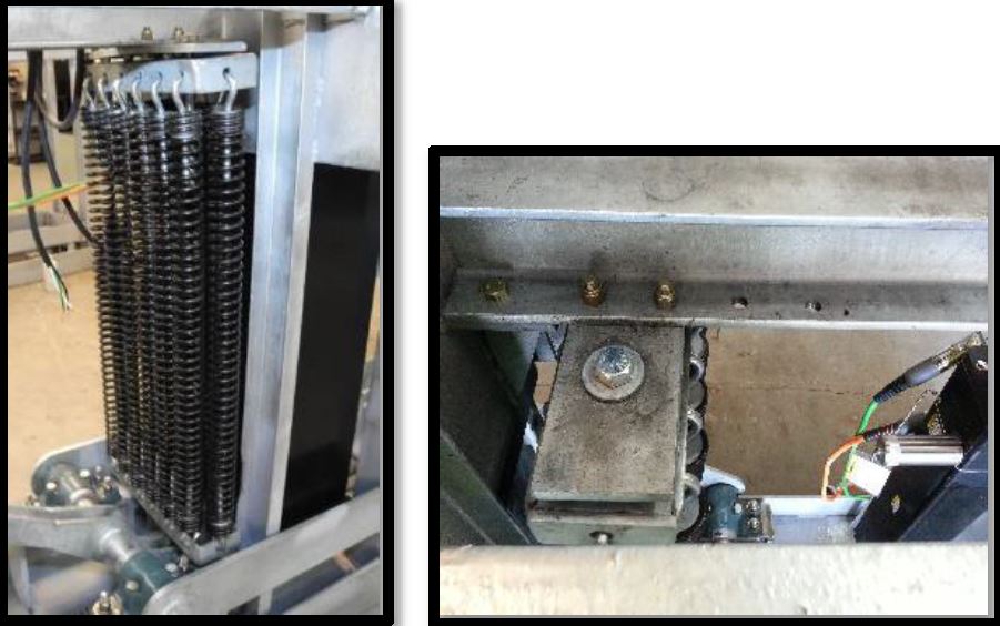
10. Check Spring Assembly. Make sure springs are not broken. Also, check the anchor bolts to<br>ensure none are loose. A loose fit or broken spring might cause excessive wear and improper<br>barrier operation.
-
-
11. Check Actuator and Spring Assembly Rod-eyes. If these connections are not kept tight, it<br>might cause loose motion that could result in excessive wear.
-
-
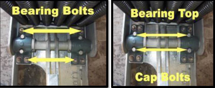
12. Check Split Journal Bearing Bolts. Make sure these are tight. A loose fit might cause<br>excessive wear and improper bollard operation.
-
Tighten bearing/ cap bolts
-
-
13. Check the unit interior for dirt and debris. Check retaining pins anchoring the barrier insert to<br>the vault (4 total). Clean or adjust as necessary.
-
14. Inspect Servo Drive Panel in barrier. a. Check cables for damage and ensure all connectors are seated properly. b. Check for corrosion on Ethernet Termination at the Servo Drive Panel. c. Check for signs of water intrusion in power connector at Servo Drive Panel. d. Check Mounting Bolts/Nuts for the Servo Drive Panel. Make sure they are tight. e. Check that Servo Drive Panel is not sitting in water (if so, re-check item #7).
- No damage or excessive wear
- Moderate wear
- excessive wear immediate attention needed
-
15. Check post assembly and touch up paint as needed.
-
16. Check the barrier interior for dirt and debris. Remove as necessary.
-
17. Replace the access cover plates and screws. Apply Permatex anti-seize lubricant or equal to screws.
-
18. Reinstate power to the barrier by turning on the Main Disconnect
-
Trouble shooting
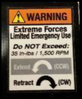
EMERGENCY MANUAL OPERATION- Use ONLY during EMERGENCY operation
-
EMERGENCY MANUAL OPERATION
-
Lowering Barrier (Open Roadway)
-
1. Determine which top plate to remove (directly over actuator)
-
-
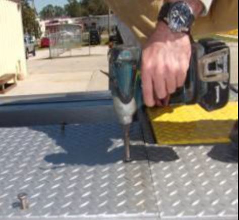
2. Using cordless impact wrench or ratchet wrench with TORX 45 bit to remove 6 top plate screws
-
-
3. Remove top plate and relocate in a safe place (plates weigh approx.. 75 lbs., use gloves and a buddy)
-
4. Using flashlight, visually inspect actuator for debris that could interfere with operation
-
WARNING
Remove power from barrier (Barrier Control Panel)
5. Disconnect power to the barrier by turning off the Main Disconnect and lock out with a wire tie or
IAW local lockout procedures. -
-
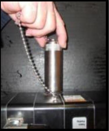
6. Remove metal cylinder cover from Manual Brake Overdrive (counterclockwise).
-
-
WARNING
NEVER use impact wrench or tool to rotate manual screw (Drill only) -
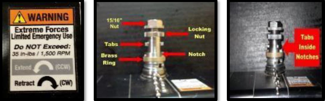
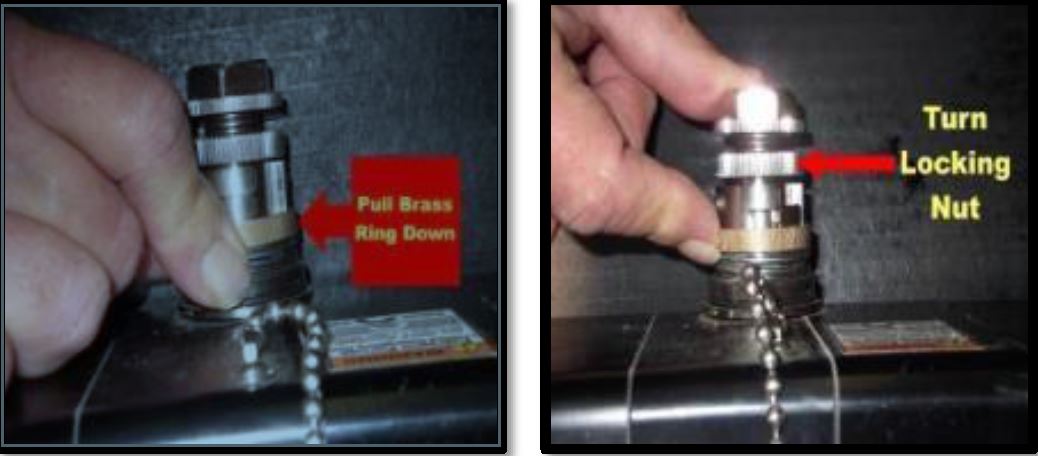
7. Hand turn the 15/16 nut clockwise while applying light pressure to engage the manual drive
downward lining up the tabs inside the notches while going down. The Brass Ring will lower and
lock as you screw down. -
-
8. Once tabs and notches are lined up and Manual Drive is down, turn locking nut (right below 15/16
nut) clockwise to Lock Manual Brake Overdrive in place. Brass ring will pop up into place. -
WARNING
NEVER use impact wrench or tool to rotate manual screw (Drill only) -
9. Switch to a cordless drill and set the drill on the slowest RPM setting. Lower the barrier by
using the drill (no pressure) and operating it on reverse setting (counterclockwise) until it reaches
the full down position. DO NOT OVERDRIVE. -
NOTE
The Manual Nut is equipped with an internal clutch. It will engage at max
physical limits or if the load is too great. -
WARNING
Improper operation of manual screw will damage actuator
10. To release Manual Drive slide the brass ring down and turn locking nut (counterclockwise) out of
notches. Then turn 15/16 nut counterclockwise to disengage Manual Drive. Manual Drive will
move upward and pop when fully disengaged. DO NOT OPERATE BARRIER UNTIL MANUAL
BRAKE OVERDRIVE IS FULLY DISENGAGED. Screw metal cylinder back onto Manual Drive
careful not to damage O-Ring or cross-thread. -
Electronic signature acknowledgement- I agree that my signature is a legally and binding equivalent to my handwritten signature. Whenever I execute an electronic signature, it has the same validity as my handwritten signature. I will not at any time in the future, repudiate the meaning of my electronic signature or claim that my electronic signature is not legally binding.
-
Hercules High Security Representative
-
Customer
-
Completion time


