


Title Page
-
PSC Self-inspection
-
Name of the ship
-
Location
-
Voyage Number
-
Entry port
-
Port ETA
-
Confirmation by 1/E
-
Confirmation by C/O
-
Confirmation by C/E
-
Conducted on (Master's Name)
-
Master's Comment
1. ISPS Check (MST, Duty officer)
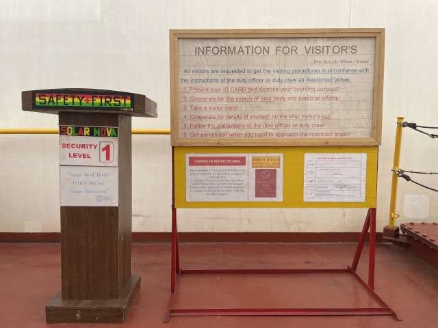
1.1 Security level display
Guide to inspection
-
instruction photo
Check Point
-
①(After arrival at port) Display Security level near Gangway
1.2 Gangway watch
Guide to Inspection
-
(ISPS, SOLAS CH-XI-2)
Watch man shall be engaged in day work for gangway watch.
Check Point
-
①Continuous strict gangway watch
-
②Prohibit standby ISPS stand under cargo loader & Crane
-
③Understand how to act when visitor entry
1.3 Visit Log
-
①Identification of visitors’ photo ID and visit log maintained, etc
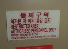
1.4 Control of restricted areas
Guide to Inspection
-
- Check the condition on locks in Eng. Room and exit to S/G room related to ship’s security and safety.
- Check the control on the entrance to restricted area (Pad locks and Seals.)
Check Point
-
①Restricted areas controlled in accordance with levels set by SSP
-
②Restriction of access to prohibited areas<br>(with the entrances sealed and/or proper measures taken, sealing or pad lock)
2. Meeting Room (MST, C/E & C/O)
2.1 Certificates (HSSC)
Guide to Inspection
-
SOLAS CH-1, Appendix (Certificate)
①Class Certificates
②SOLAS Certificates (SC, SE, SR, ISM, ISPS Cert.)
③MARPOL Certificate (IOPP, IAPP, ISPP, IAFS)
④Load Line Certificate
⑤ Safety Manning Cert.
⑥ LC Certificate
- Officer & Crew Certificates (According to SMC, STCW)
- Listing the valid dates per each certificates.(Recommendation)
- Record on SE certificate (check with Form E)
Check Point
-
①Validity, Contents any defect see the [List of Certificate] [Status of Crew Qualification]
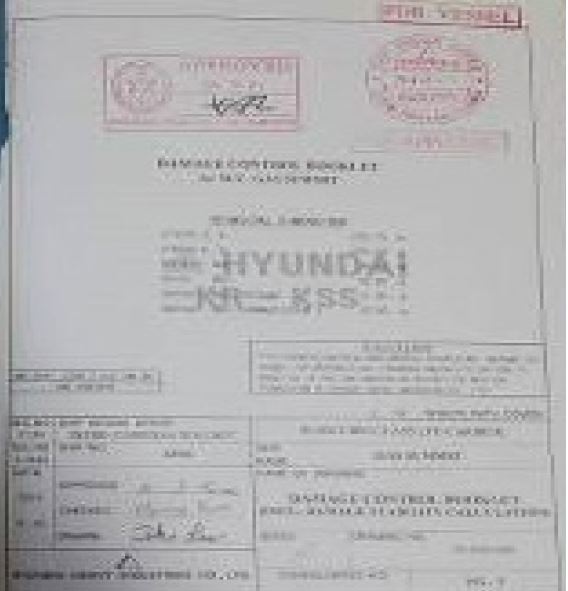
2.2. Stability booklet, grain loading manual
Guide to Inspection
-
SOLAS CH-VI CARRIAGE OF CARGOES AND OIL FUELS
cargo hold as specified in regulation 5.1 and the standards and criteria for side structures of bulk carriers of single-side skin construction, adopted by the Organization by resolution MSC.168(79), shall not sail with any hold loaded to less than 10% of the hold’s maximum allowable cargo weight
when in the full load condition, after reaching 10 years of age. The applicable full load condition for this regulation is a load equal to or greater than 90% of the ship’s deadweight at the relevant assigned freeboard.
(SOLAS 74, 2014)
Strength of the inner bottom plating could be deteriorated due to corrosion wastage. The operational parameters and tank top strength(T/m2) of the effected vessels may be updated by the classification society.
Check Point
-
①Original copy on board
-
②Loadcom annual test by Classification
-
②Loadcom annual test by Classification (Recorded the last date)
2.3 Survey report file (ESP only)
Guide to Inspection
-
SOLAS CH-I, Reg.10 Surveys of structure, machinery and equipment of cargo ships
(*ESP : Enhanced Survey Programme for bulk carriers, Crude oil tankers and chemical tankers. It belongs to the ships with certificate remarked ESP)
The latest version shall be downloaded through Class homepage.
Check Point
-
①Classification Report<br>(Tank Survey Report, EH/Executive Hull Summary)
-
②TM/Thickness measure report
-
③Survey Program(Until completion)
2.4 SOPEP
Guide to Inspection
-
MARPOL/ Annex I / Reg. 37, Shipboard oil pollution emergency plan
Every ship other than an oil tanker of 400 gross tonnage and above shall carry on board a shipboard oil-pollution emergency plan approved by the Administration.
Such a plan shall be prepared based on guidelines developed by the Organisation and written in the working language of the Master and officers. The plan shall consist at least of:
> The procedure to be followed by the Master or other persons having charge of the ship to report an oil pollution incident
> The list of authorities or persons to be contacted in the event of an oil pollution incident
> A detailed description of the action to be taken immediately by persons on board to reduce or control the discharge of oil following the incident
> The procedures and point of contact on the ship for coordinating shipboard action in combating the pollution with national and local authorities
> Description of equipment, its location, a plan for deployment and specific crewmember duties for handling small spills, and
> An up-to-date IMO Coastal Contact List.
Check Point
-
①Updated list of national operational contact list<br>ANNEX II: Every quarters (Date 1/31, 4/30, 7/31, 10/31) MSC-MEPC.6/Circ.22
-
②Oil spill kit update (Every Month)
-
③Flag Approval
2.5 Oil record book (ORB)
Guide to Inspection
-
MARPOL / Annex I / Reg.17, Oil Record Book, Part I - Machinery space operations MEPC1_Circ736/Rev.2]
(Especially, Comparison with Sound Log Book and ORB)
- IOPP Certificates, Tank names and Sizes
- Sludge incineration quantity (Quantity of Discharge ashore shore. / on board )
- Incinerator operation time record (Start / End)
Check Point
-
①Accurate entries
-
②Incinerated residue q’ty (to shore/on board)
-
③Bilge q’ty
-
④BDN
2.6 Garbage management plan (GMP) & Garbage record book (GRB)
Guide to Inspection
-
MARPOL / Annex V / Reg. 10 Placards, garbage management plans and garbage record-keeping
Check Point
-
①To be on board
-
②Accurate GRB, Kept a shore facility landing certificate
-
③Display the placards<br>W/H, Galley, A-DK(officer's mess RM, Crew's mess RM, Corridor), Uppder DK(P/S Entrance), Garbage store, Garbage collecting drum ECR, Incinerator
-
④Minimization, Segregation
2.7 Ballast water management plan &Ballast water record book
Guide to Inspection
-
BWM / ANNEX / Regulation B-1
Ballast Water Management Plan
B-2 Ballast Water Record Book
Mis-matching between BWRB, Ballast log
Miss the record the familarization
Check Point
-
①Approved BWMP & Certificate For Panama Flag : Classification annual endorsement
-
②Accurate BWRB
-
③Crew training & Familiarization
2.8 Rest Hours of Crew
Guide to Inspection
-
MLC Reg.2.3 Hours of work and hours of rest
- when ship arrival/departure procedures,
- transit of narrow channels
- crews’ drill and training
- bunker oil receiving operations
- Calling while off-duty due to UMA
** Minimum break time shall be more than 10 hours of 25 hrs, which shall not be divided more than twice and one of them shall be at least six hours.
- Exemption
① Calling while off-duty due to UMA cause interrupt normal break time
② Implementation of master’s instructions for instant of ship, life and cargo or saving life at distress.
Check Point
-
①Minimum rest hours properly provided to crews
2.9 MLC related matters
Guide to Inspection
-
MLC Reg.2.1 Seafarers' employment agreements
MLC Reg.5.1.5 – On-board complaint procedures
(full payment of wages and Medical care provided)
Check Point
-
①Seafarers' employment agreements
-
②Complaint Procedure onboard and provided to seafarers
2.10 Cargo information
Guide to Inspection
-
SOLAS / Chapter VI / Reg. 2 Cargo information
SOLAS / Chapter VI / Reg. 7 Loading, unloading and stowage of solid bulk cargoes
- MSDS/Material Safety Data Sheet
- BCI/Bulk Cargo Information(IMO's Bulk Cargo Shipping Name - BCSN).
- Moisture & TML(Transportable Moisture Limit) Certificate
Check Point
-
①Verified Cargo evidences <br><br>- MSDS/Material Safety Data Sheet<br>- BCI/Bulk Cargo Information(IMO's Bulk Cargo Shipping Name - BCSN). <br>- Moisture & TML(Transportable Moisture Limit) Certificate
-
②Loading/Unloading plan (monitoring, Signature)
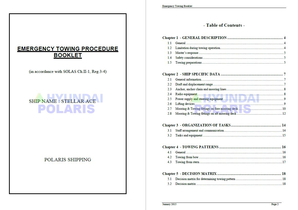
2.11 Emergency Towing Arrangement
Guide to Inspection
-
SOLAS / Chapter II-1 / Reg. 3-4.1, MSC.1/Circ.1255
Matching with ship's particular (GMDSS Equipment, Mooring equipment & etc)
Check Point
-
①Updated ETA (Bridge, F’cle, Office or CCR)
2.12 PSC report
Guide to Inspection
-
IMO Res.A. PROCEDURES FOR PORT STATE CONTROL
Check Point
-
①Outstanding Deficiencies on the last report
2.13 Drills
Guide to Inspection
-
SOLAS CH-II-1,Reg.3-4
SOLAS CH-III Reg.19
SOLAS CH-III,Reg.17-1
SOLAS CH-V,Reg.26
MARPOL Ann I Reg.37
ISM
Check Point
-
①Drill conduct and recording <br> - SMS [Annual plan for Drill & Training] (ISM, ISPS)
-
②Content of training <br> - PSCO may be pointed out if not recorded convention's requirement<br> - Record log book, Training record
3. Bridge (Deck Officer)
3.1 Chart(ENC) & Notice to Mariner
Guide to Inspection
-
SOLAS CH-V,Reg.19.2.1.4
.4 nautical charts and nautical publications to plan and display the ship's route for the intended voyage and to plot and monitor positions throughout the voyage. An electronic chart display and information system (ECDIS) is also accepted as meeting the chart carriage requirements of this subparagraph. Ships to which paragraph 2.10 applies shall comply with the carriage requirements for ECDIS detailed therein; (Replaced by Res.MSC.282(86))
SOLAS CH-V,Reg.24
Nautical charts and nautical publications, such as sailing directions, lists of lights, notices to mariners, tide tables and all other nautical publications necessary for the intended voyage, shall be adequate and up to date. -
①Charts
-
②Latest edition & small correction
-
③AIO, T&P
3.2 Publication(E-Publication)
Guide to Inspection
-
** SOLAS Ch.V Regulation 27 “Nautical charts and nautical publications, such as
sailing directions, lists of lights, notices to mariners, tide tables and all other
nautical publications necessary for the intended voyage, shall be adequate and up
to date.”. Refer to MSC-MEPC.2/Circ.2 -
①Lights list, Tide table, Sail. Dir. Latest edition & Small corr.
-
②IAMSAR Manu.(Every 3years), International Code of Signals (Hard Copy)
3.3 Deck log book/Training Record
Guide to Inspection
-
SOLAS CH-III, Reg.19
SOLAS CH-V,Reg.26
** Fire Fighting/Abandon Ship: Once a month (SOLAS 2006 Amend Reg.III/19)
** Passenger ship : once a week회
Lifeboat launching drill : every three months
Rescue boat launching drill : once a month
Free-fall lifeboat launching drill : every six month
Entering enclosed area drill: once per two month (1 / two month)
Em’cy Steering drill : every three months (SOLAS 1999/2000 Amend / Ch.V/26)
Oil pollution response drill: once a month.
** Emergency Drills are required at least once a year according to KR rule Part2
Drills belonging to the convention are subject to SOLAS convention.
Fire/Explosion/Collision/Aground/Flood/Life -saving/Pollution/Steering Failure
/Loss of propulsion /Injuries/
Abandon Ship/Entering enclosed area and rescue/Ship-shore joint drills
** In case of 25% of crew change, concerned drills up to each type of ships are
distinguished. -
①Drill records (To be recorded last date of drills) <br>- Abandon ship/Fire drill-1M<br>- Lifeboat launching, maneuvering -3M (Rescue boat 1M)<br>- Em’cy steering drill-3M<br>- Entering to enclosed spaces-2M & etc.)
-
②Confirmation that drill details in deck log book is in accord with training records files
3.4. Passage Plan
Guide to Inspection
-
SOLAS / Chapter V / Reg. 34
Safe navigation and avoidance of dangerous situations
1 Prior to proceeding to sea, the master shall ensure that the intended voyage has been planned using the appropriate nautical charts and nautical publications for the area concerned, taking into account the guidelines and recommendations developed by the Organization* .
2 The voyage plan shall identify a route which:
.1 takes into account any relevant ships' routeing systems;
.2 ensures sufficient sea room for the safe passage of the ship throughout the voyage;
.3 anticipates all known navigational hazards and adverse weather conditions; and
.4 takes into account the marine environmental protection measures that apply, and avoids as far as possible actions and activities which could cause damage to the environment.
STCW Code Part A / Part 2, Res.A.893(21) -
①Berth to Berth
-
②Port Regulation(Environment, Traffic, UKC, etc)
-
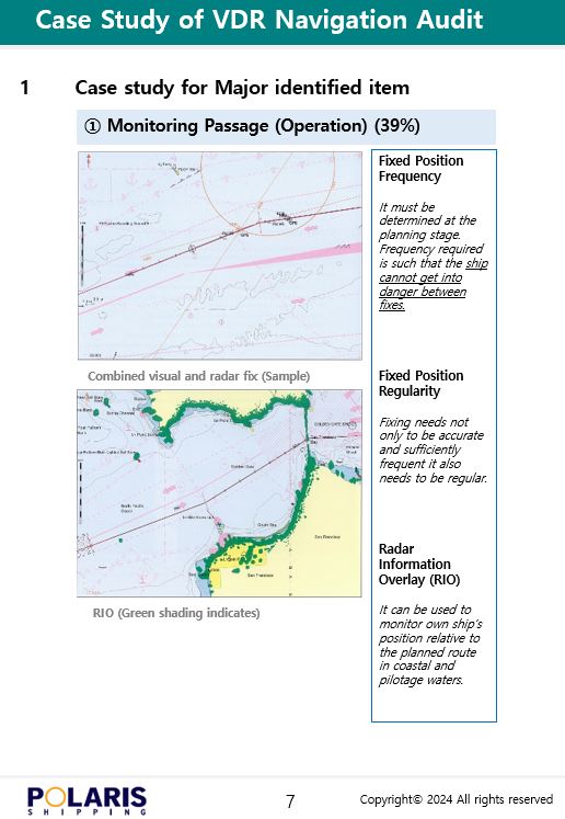
③Monitoring of Passage plan(P.I., Position fixing)
-
④Evaluation of Passage plan after completion
-
⑤Proper Recording chronological
3.5 Standard magnetic compass
Guide to Inspection
-
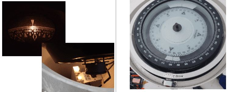
SOLAS / Chapter V / Reg. 19.2.1
2.1 All ships irrespective of size shall have:
.1 a properly adjusted standard magnetic compass, or other means, independent of any power supply to determine the ship's heading and display the reading at the main steering position;
.2 a pelorus or compass bearing device, or other means, independent of any power supply to take bearings over an arc of the horizon of 360 degrees -
①Lighting
-
②No bubble
-
③Deviation table (Last date)
-
④Spare magnetic compass (if,fitted)
3.6 VHF, MF/HF radio
Guide to Inspection
-
SOLAS / Ch-IV / Reg. 12 Watches
- Shore Based Maintenance Company Guide - At the China Area
1) Select SSB (or J3E, TELEPHONE) in MF/HF and select CHANNEL 1225.
2) Afterwards, press ANT TUNE and when tuning is complete, press MIC (or HANDSET) KEY and call Guangzhou RADIO.
3) When Guangzhou RADIO responds, they conclude by saying that they are testing the equipment.
Note) CHANNEL frequency 1225 (If you select CHANNEL, the frequency appears automatically.)
Tx: 12,302KHz Rx: 13,149KHz -
①BQ/RQ test in Em’cy/Reserve of power & report - BQ (ACK Back quest), RQ (ACK Request)
-
②Familiarization
-
③MF/HF SSB(Single Side Band Radio) Test call
-
④VHF DSC TEST CALL
-
⑤Two-way VHF test call & Battery expire date
3.7 EPIRB
Guide to Inspection
-
SOLAS / Ch- IV / Reg. 7.1.5
.5 an EPIRB14 which shall be:
14 Refer to Search and rescue homing capability (resolution A.616(15)).
.1 installed in an easily accessible position;
.2 ready to be manually released and capable of being carried by one person into a survival craft;
.3 capable of floating free if the ship sinks and of being automatically activated when afloat; and
.4 capable of being activated manually; and
** Issued by EPIRB Shore-Based Maintenance Provider (MSC Circ.1039) -
①Test
-
②Valid date of HRU & Battery expire date
-
③Location (Resetting Condition)
3.8 SART
Guide to Inspection
-
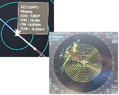
SOLAS / Ch IV / Reg. 7.1.3
-
①Test (Caution near ship's density)
-
②Battery expire date
3.9 AIS
Guide to Inspection
-
SOLAS / Ch V / Reg. 18.9
9 The automatic identification system (AIS) shall be subjected to an annual test. The test shall be conducted by an approved surveyor or an approved testing or servicing facility. The test shall verify the correct programming of the ship static information, correct data exchange with connected sensors as well as verifying the radio performance by radio frequency measurement and on-air test using, e.g., a Vessel Traffic Service (VTS). A copy of the test report shall be retained on board the ship.
MSC.1/Circ.1252 -
①Check the ship's information and status
3.10 Echo Sounder
Guide to Inspection
-
SOLAS / Ch V / Reg. 19.2.3 RESOLUTIONs / MSC Resolutions / Res.MSC.74(69)
5.2 Accuracy
5.2.1 Accuracy of measurement
Based on a sound speed in water of 1,500 m/s, the tolerance of the indicated depth should be either:
- +/- 0.5 m on the 20 m range scale, respectively +/- 5 m on the 200 m range scale; or
- +/- 2.5% of the indicated depth, whichever is greater. -
①Alarm set
-
②Verify the error
3.11 (S)VDR
Guide to Inspection
-
SOLAS / Ch V / Reg.18.8
8 The voyage data recorder system, including, all sensors, shall be subjected to an annual performance test. The test shall be conducted by an approved testing or servicing facility to verify the accuracy, duration and recoverability of the recorded data. In addition, tests and inspections shall be conducted to determine the serviceability of all protective enclosures and devices fitted to aid location. A copy of the certificate of compliance issued by the testing facility, stating the date of compliance and the applicable performance standards, shall be retained on board the ship. -
①Familiarization(VDR Back-up each case)
-
②Any defect alarm
-
③Control and management by Master
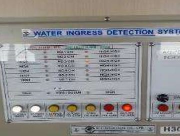
3.12 Water Ingress System
Guide to Inspection
-
SOLAS / Ch XII / Reg. 12.
SOLAS / Ch II-1 / Reg.25.
** This regulation is subject to the Bulk Carriers such as Ore carriers specified on SOLAS XII.
Single hold cargo ships other than bulk carriers shall be fitted water level detectors according to SOLAS II-1/25 -
①Any abnormal alarm - Sound, buzzer, indicator
-
②Any abnormal alarm tested date - Sound, buzzer, indicator
3.13 Daylight signal lamp
Guide to Inspection
-
SOLAS / Ch V / Reg. 19.2.2
All ships of 150 gross tonnage and upwards shall be fitted with a signalling daylight lamp, or other means to communicate by light during day and night using an energy source of electrical power not solely dependent upon the ship’s power supply (Reg.V/19.2.2 in SOLAS 2000 amendments ) -
①Operation by Em’cy power (Battery)
-
②Operation at both ship sides
-
③Portable battery and at least 3 spare illuminants
3.14 Fire alarm & fire detection system
Guide to Inspection
-
SOLAS CH-II-2, Reg.13.
** FSS code Chapter .9 /2.5
The activation of any detector or manually operated call point shall initiate a visual and audible fire detection alarm signal at the control panel and indicating units.
If the signals have not been acknowledged within 2 min, an audible fire alarm shall be automatically sounded throughout the crew accommodation and service spaces, control stations and machinery spaces of category A. This alarm sounder system need not be an integral part of the detection system ** Manually operated call points shall be installed throughout the accommodation spaces, service spaces and control stations. One manually operated call point shall be located at each exit. Manually operated call points shall be readily accessible in the corridors of each deck such that no part of the corridor is more than 20 m from a manually operated call point. (SOLAS 1983 Amend/ II-2, Reg.13.2) -
①Any abnormal alarm
-
②Test by Em’cy power
-
②Test by Em’cy power
-
③Alarm (Visual, audible acknowledge 2 min & relay)
-
④MCP’s Distance (Not exceed 20m)
-
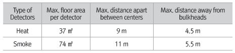
⑤Detector’s distance (Max. Heat 9m / Smoke 11m)<br>- Bulkhead away : Heat 4.5m, Smoke 5.5m
-
⑥Check for control fault alarm cleared
-
⑦Test (as planned schedule)
3.15 Navigation light & Signal light
Guide to Inspection
-
COLREG / Part C / Part D
In case of loss of main source, emergency source shall be provided to navigation lights as quickly as is safe and practicable.
Unless emergency generator starts supplying the required load within 45 sec, the ship shall be provided with a transitional source of emergency electrical power
NAVIGATION LIGHT PANEL (SOLAS Ch.II-1, Reg.43. 3, 4) -
①Light on/off test, Alarm test
-
②Any Covered by painting or damage/broken
-
③By Em’cy power
-
④Light angle
-
⑤Christmas light

3.16 Emergency lighting
Guide to Inspection
-
SOLAS / Ch II-1 / Reg. 43
2.3 For a period of 18 h :
.1 the navigation lights and other lights required by the International Regulations for Preventing Collisions at Sea in force ;
.2 on ships constructed on or after 1 February 1995 the VHF radio installation required by regulation IV/7.1.1 and IV/7.1.2 ;and if applicable :
.1 the MF radio installation required by regulations IV/9.1.1,IV/9.1.2,IV/10.1.2 and,IV/10.1.3 ;
.2 the ship earth station required by regulation IV/10.1.1 ;and
.3 the MF/HF radio installation required by regulations IV/11.1.1 and IV/11.1.2. ( -
①Functioning, No damage
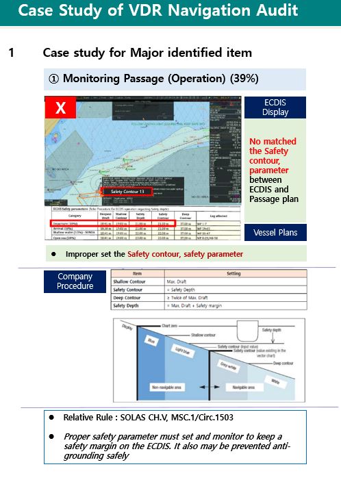
3.17 ECDIS
Guide to Inspection
-
SOLAS / Ch V / Reg. 19.2.1, STCW CH VIII, STANDARDS REGARDING WATCHKEEPING
1. Officer education: Division between Generic and Familiarization (TypeSpecification).
2. Generic education by training center - Module training (Certificate on board)
: According to STCW convention, the officers of the vessels fitted with ECDIS shall be required to be certified according to STCW Table A-II/1.
3. Familiarization training shall be carried out with the materials provided by maker and Record the education/training and result. -
① ENC License expire & Version of ENCs
-
②Proper setting <br>- Safety Depth, contour <br>- Safety detection <br>- Cross track distance <br>- Shade <br>- AIO<br>- Route display <br>- Radar, AIS Overlay
-
③Familiarization of Deck Officers & training record<br>[Familiarization with ECDIS]
-
④Familiarization of Emergency Response for ECDIS<br>- Sensor failure cases<br>- ECDIS failure case
-
⑤Operation under both main and emergency source of power, etc.
-
⑥Periodical backup (3M)
3.18 BNWAS
Guide to Inspection
-
SOLAS / Ch V / Reg. 19.1.2, Res.MSC.128(75)
The BNWAS must be operational whenever the ship is underway and should be used at anchor. Use of Bridge Navigational Watch Alarm System (BNWAS) modes (automatic, manual, on and off) and procedures for ensuring correct operation should be incorporated in the company navigation procedure.
The peration of the BNWAS should be part of the departure checklist and a key,if supplied, should be kept with the Master when switched on.
(Bridge Procedure Guide, 2022) If a failure (e.g., internal communication failure) of, or power supply failure to, the BNWAS is detected, it is to be indicated by visual and audible alarms. Means are to be provided to allow the repeat of this indication on a central alarm panel, if fitted.
The means of selecting the Operational Mode and the duration of the Dormant Period should be security protected so that access to these controls should be restricted to the master only. The BNWAS should be powered from the ship’s main power supply. The malfunction indication, and all elements of the Emergency Call facility, if incorporated, should be powered from a battery-maintained supply.
If a malfunction of, or power supply failure to, the BNWAS is detected, this should b -
①Proper set
-
②Keeping the Password, controlled by Master
-
③Alarm
3.19 Watch keeping schedules(for ship underway or at port)/Muster list
Guide to Inspction
-
MLC Reg.2.3.
① Duty Table shall be Displayed
② Minimum break time shall be observed -
①Watch keeping schedules(procedures) and muster list are established and posted on the bridge
-
②The number of personnel on board is considered in such lists.
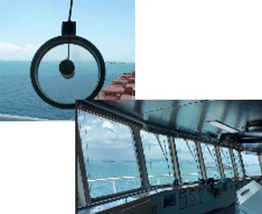
3.20 Bridge Visibility
Guide to Inspection
-
SOLAS / Ch V / Reg.22
2 No blind sector caused by cargo, cargo gear or other obstructions outside of the wheelhouse forward of the beam which obstructs the view of the sea surface as seen from the conning position, shall exceed 10 degrees. The total arc of blind sectors shall not exceed 20 degrees. The clear sectors between blind sectors shall be at least 5 degrees. However, in the view described in .1, each individual blind sector shall not exceed 5 degrees;
.9.4 A clear view through at least two of the navigation bridge front windows and, depending on the bridge configuration, an additional number of clear-view windows shall be provided at all times, regardless of weather conditions. -
①Bridge window wiper & Clear view screen
-
②Operation of Heater
3.21 Deck officers familiarization with navigation equipment
Guide to Inspection
-
Deck officer familiarization with navigation equipment should be delivered one-on-one using a common language using the Bridge Procedure Guide’s (BPG) checklist C2.3 and C2.4. Familiarization should include all bridge equipment and procedures relevant to the roles and responsibilities of each bridge team member. (Bridge Procedure Guide, 2022)
-
①Familiarization of Deck officers with navigational equipment operating and maintenance [Familiarization with Bridge equipment] - STCW CH VIII
4. Outside of Accommodation (C/O, Engineers)
4.1 Battery room
Guide to Inspection
-
SOLAS / CH-IV / Reg.13
SOLAS CH-II-2/Reg.5.2.1.1. / IACS UI SC 240
Battery room marking
“The main inlets and outlets of all ventilation systems shall be capable of being closed from outside the spaces being ventilated. The means of closing shall be easily accessible as well as prominently and permanently marked and shall indicate whether the shut-off is open or closed. “
Marking the following phrase around the Batter RM vent (or similar phrase)
- This closing device is to be kept open and only closed in the event of fire or other emergency – Explosive gas -
①Reserve cond. for GMDSS & Battery on/off load test
-
①Reserve cond. for GMDSS & Battery on/off load test
-
②Recharging
-
③Connecting cable
-
④Explosion-proof lamp
-
⑤Battery expired date
-
⑥Proper PPE standby (avoid possible contamination)
4.2 Em’cy generator room
Guide to Inspection
-
SOLAS / CH II-1 / Reg. 44
.3 all of these starting, charging and energy storing devices shall be located in the emergency generator space; these devices are not to be used for any purpose other than the operation of the emergency generating set. This does not preclude the supply to the air receiver of the emergency generating set from the main or auxiliary compressed air system through the non-return valve fitted in the emergency generator space.
If the vessel is trading in area with sub-zero temperature, the fuel tank of the emergency generator should be charged with fuel designed for use in sub-zero temperatures.
> The generator should be capable of providing full load requirements for at least 18 hours.
> Every oil fuel pipe (which, if damaged, would allow oil to escape from a storage, settling or daily service tank situated above the double bottom) shall be fitted with a cock or valve directly on the tank capable of being closed from a safe position, outside the space concerned, in the event of a fire occurring in the space in which such tanks are situated.
> Oil fuel pipes (which, if damaged, would allow oil to escape from a storage, settling or daily service tank having a capacity of 500 litres and above situated above the double bottom) shall be fitted with a cock or valve directly on the tank capable of being closed from a safe position, outside the space concerned, in the event of a fire occurring in the space in which such the tanks are situated.
> The controls for the remote operation of the valve for the emergency generator fuel tank shall be in a separate location from the controls for the remote operation of other valves for tanks located in machinery spaces. -
①Functioning
-
②Gauges, indicators
-
③Fuel oil tank quick closing valve condition
-
④Fuel q’ty (To be operated for 18 hours)
-
⑤Blackout test(test mode) ACB testing
-
⑤Blackout test(test mode) ACB testing (Date)
-
⑥Check Earth (During turn of deck light)
4.3 E/R ventilator & E/R funnel flap (damper)
Guide to Inspection
-
SOLAS / CH II-2 / Reg.9
SOLAS Reg. II-2/5.2.2.1 "means of control are to be provided for closure of openings in funnels which normally allow exhaust ventilation and closure of ventilation dampers".
There are NO requirements for the dampers located in the engine room funnels to be of the gastight or watertight type (normally these dampers are located higher than 2.3 m above position 2 and accordingly they are not required to be watertight in accordance with Load Line requirements).
The funnel flaps are not for forced ventilation they are a natural means of exhaust. Once they are closed and ER ventilation shutdown there is no air flow, and therefore no pressure differential across the dampers and if CO2 is released into the machinery space it flows to the lower levels as it is heavier than air. -
①Damper moving/corrosion
-
②Maintenance considering manufacturer’s gap standard
-
③Visual check the flap
-
④No Leakage from Control air line
4.4 Lighting (Emergency)
Guide to Inspection
-
SOLAS / CH II-1 / Reg. 41
-
①Working condition
4.5 Air pipe & Sounding
Guide to Inspection
-
ICLL / Annex I / Chapter II / Reg. 20
Where air pipes to ballast and other tanks extend above the freeboard or superstructure decks, the exposed parts of the pipes shall be of substantial construction; the height from the deck to the point where water may have access below shall be at least 760 mm (30 inches) on the freeboard deck and 450 millimetres ( 17½ inches) on the superstructure deck. Where these heights may interfere with the working of the ship, a lower height may be approved, provided the Administration is satisfied that the closing arrangements and other circumstances justify a lower height. Satisfactory means permanently attached, shall be provided for closing the openings of the air pipes. -
①Marking
-
②Air pipe head, ball, floater damage
-
③Any missing of sounding cap
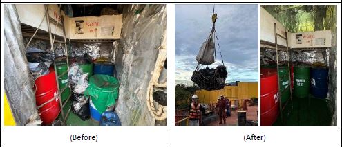
4.6 Garbage management & Garbage storage
Guide to Inspection
-
MARPOL / Annex V / Reg. 10
Garbage collected throughout the ship should be delivered to designated processing or storage locations. Cleaning and disinfecting of garbage storage location are both preventative and remedial pest control methods that should be applied regularly in garbage storage areas.
SOLAS CH II-2, Reg.4.4 / 4.2 Waste receptacles Go!IACS UI SC 166
Waste receptacles shall be constructed of non-combustible materials with no openings in the sides or bottom. -
①Garbage storage - If exessive of garbage, request to be landing to shore
-
②Segregation, Minimizing
-
③Proper marking & Display <br>- Category, Placard
5. Survival Craft & Launching arrangements (C/O, 2/O, 2/E & 3/E)
5.1 Inflatable liferaft
Guide to Inspection
-
SOLAS / CH-IV, 4.2.
Cargo ships shall carry one or more inflatable or rigid liferafts, stowed in a position providing for easy side-to-side transfer at a single open deck level and of such aggregate capacity as will accommodate the total number of persons on board. If not stowed in a position providing for easy side-to-side transfer at a single open deck level, the total capacity available on each
side shall be sufficient to accommodate the total number of persons on board.
If a free-fall lifeboat is fitted, cargo ships shall have one or more inflatable or rigid liferafts, on each side of the ship, of such aggregate capacity as will accommodate the total number of persons on board. The liferafts on at least one side of the ship shall be served by launching appliances.
For davit launched liferafts, the launching appliance shall include an automatic release hook arranged so as to prevent premature release during lowering and shall release the liferaft when waterborne. The release hook shall include a capability to release the hook under load. The on-load release control shall:
> Be clearly differentiated from the control which activates the automatic release function;
> Require at least two separate actions to operate;
> Be designed such that crew members on deck can clearly observe when the release mechanism is properly and completely set.
Every liferaft shall be stowed with its painter permanently attached to the ship.
Each liferaft or group of liferafts shall be stowed with a float-free arrangement so that each floats free and if inflatable, inflates automatically when the ship sinks.
Liferafts shall be so stowed as to permit manual release of one raft or container at a time from their securing arrangements.
Some hydrostatic release manufacturers recommend that each liferaft is fitted with its own individual hydrostatic release unit (HRU), to prevent the possibility, where more than one liferaft is utilising the same release, of one of the liferafts breaking the weak link before the second or subsequent liferafts have inflated.
When multiple liferafts are connected to a single HRU, each raft must be equipped with its own weak link. A HRU is not required for liferafts stored in the forward part of a vessel.
Check point
-
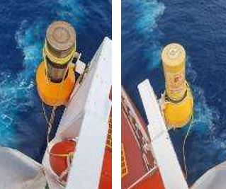
①HRU & Expired date
-
②Movable(if applicable)
-
③Weak Link connection
-
④Clear instruction
-
⑤Any obstruction above
-
⑥Drain hole condition (Position)
-
⑦Marking(Port of Registry, Ship Name)
5.2 Annual thorough exam. By shore technician
Guide to Inspection
-
SOLAS / CH 1
Check Point
-
①Report and filing<br> (clean without any recommendation or any remark)
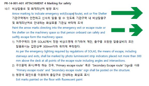
5.3 Access (escape) route
Guide to Inspection
-
SOLAS / CH II-2 / Reg.13
Check Point
-
①No obstacle on the way
-
②Clear marking & symbol
5.4 Lifeboat (Freefall)
Guide to Inspection
-
LSA / CH IV/ Reg.4.7
Each survival craft shall be stowed in a state of continuous readiness so that two crew members can carry out preparations for embarkation and launching in less than five minutes.
Falls used in launching shall be inspected periodically with special regard for areas passing through sheaves and renewed when necessary due to deterioration of the falls or at intervals of not more than five years – whichever is the earlier.
Each free-fall lifeboat shall be fitted with a release system which shall be designed to test the release system without launching the lifeboat.
Each lifeboat shall be clearly marked with the number of persons for which the lifeboat is approved and the name and port of registry. Means of identifying the ship to which the lifeboat belongs, and the number of the lifeboat shall be marked in such a way that they are visible from above.
The release system of lifeboats, rescue boats, free-fall lifeboat including davit-launched life rafts shall be:
> Maintained in accordance with instructions for on-board maintenance as required by regulation 36.
> Subjected to a thorough examination and operational test during the annual surveys required by regulations I/7 and I/8 by properly trained personnel familiar with the system; and
> Operationally tested under a load of 1.1 times the total mass of the lifeboat when loaded with its full complement of person and equipment whenever the release gear is overhauled. Such over-hauling and testing shall be carried out at least once every five years.
Davit-launched life raft automatic release hooks shall be:
> Maintained in accordance with instructions for on-board maintenance as required by regulation 36.
> Subjected to a thorough examination and operational test during the annual surveys required by regulations I/7 and I/8 by properly trained personnel familiar with the system; and
> Operationally tested under a load of 1.1 times the total mass of the lifeboat when loaded with its full complement of person and equipment whenever the release gear is overhauled. Such over-hauling and test shall be carried out at least once every five years.
Check Point
-
①Hull condition(including Skate Pender, Bilge keel etc)
-
②Clear Hull Marking
-
③Retro taping
-
④Window sight
-
⑤Running(3 min.) & Propulsion(FWD/AFT, full speed)
-
⑥F.O level & Tk
-
⑦Battery recharged(if required)
-
⑧Two independent engine starting system
-
⑨Internal in L/boat
-
⑩Search light, nav. Light
-
⑪Fire extinguisher
-
⑫Expired date Food ration, drinking water, anti-seasickness pills & Other inventory
-
⑬Magnetic compass bubble & error
-
⑭Release hook Correct re-setting (according to instruction)
-
⑮Recovery condition
-
⑯Access (Clear without any obstruction, No locking)
5.5 Rescue boat
Guide to Inspection
-
LSA / CH V
5.1.2 Rescue boat equipment
5.1.2.1 All items of rescue boat equipment, with the exception of boat-hooks which shall be kept free for fending off purposes, shall be secured within the rescue boat by lashings, storage in lockers or compartments, storage in brackets or similar mounting arrangements, or other suitable means. The equipment shall be secured in such a manner as not to interfere with any launching or recovery procedures. All items of rescue boat equipment shall be as small and of as little mass as possible and shall be packed in suitable and compact form.
5.1.2.2 The normal equipment of every rescue boat shall consist of:
.1 sufficient buoyant oars or paddles to make headway in calm seas. Thole pins, crutches or equivalent arrangements shall be provided for each oar. Thole pins or crutches shall be attached to the boat by lanyards or chains;
.2 a buoyant bailer;
.3 a binnacle containing an efficient compass which is luminous or provided with suitable means of illumination;
.4 a sea-anchor and tripping line if fitted with a hawser of adequate strength not less than 10 m in length;
.5 a painter of sufficient length and strength, attached to the release device complying with the requirements of paragraph 4.4.7.7 and placed at the forward end of the rescue boat;
.6 one buoyant line, not less than 50 m in length, of sufficient strength to tow a liferaft as required by paragraph 5.1.1.7;
.7 one waterproof electric torch suitable for Morse signalling, together with one spare set of batteries and one spare bulb in a waterproof container;
Refer to MSC.1/Circ.1674 UNIFIED INTERPRETATION OF THE LSA CODE AND THE 1994 AND 2000 HSC CODES
.8 one whistle or equivalent sound signal;
.9 a first-aid outfit in a waterproof case capable of being closed tightly after use;
.10 two buoyant rescue quoits, attached to not less than 30 m of buoyant line;
.11 a searchlight with a horizontal and vertical sector of at least 6° and a measured luminous intensity of 2500 cd which can work continuously for not less than 3 h;
.12 an efficient radar reflector;
.13 thermal protective aids complying with the requirements of section 2.5 sufficient for 10% of the number of persons the rescue boat is permitted to accommodate or two, whichever is the greater; and
.14 portable fire-extinguishing equipment of an approved type suitable for extinguishing oil fires.*
*Refer to the Improved Guidelines for marine portable fire extinguishers, adopted by the Organization by resolution A.951(23).
5.1.2.3 In addition to the equipment required by paragraph 5.1.2.2, the normal equipment of every rigid rescue boat shall include:
.1 a boat-hook;
.2 a bucket; and
.3 a knife or hatchet.
5.1.2.4 In addition to the equipment required by paragraph 5.1.2.2, the normal equipment of every inflated rescue boat shall consist of:
.1 a buoyant safety knife;
.2 two sponges;
.3 an efficient manually operated bellows or pump;
.4 a repair kit in a suitable container for repairing punctures; and
.5 a safety boat-hook.
Check Point
-
①Hull condition
-
②Clear Hull Marking
-
③Retro taping
-
④Inventory (Any defect, expired, short of item)
-
⑤Running(3 min.) & Propulsion(FWD/AFT, full speed)
-
⑥F.O level & Tk
-
⑦Battery recharged(if required)
-
⑧Two independent engine starting system
-
⑨Any damage
-
⑩Light
-
⑪Fire extinguisher
5.6.1 Davit (lifeboat, rescue boat)
Guide to Inspection
-
LSA / CH IV/ Reg.4.7 & LSA / CH V
Check point
-
①Excessive corrosion
-
②Limit Switch
-
③Greasing for moving part
5.6.2 Davit (Davit-launched liferaft)-if fitted
Guide to Inspection
-
LSA / CH IV
Check Point
-
①Excessive corrosion
-
②Limit Switch
-
③Greasing for moving part
-
④Lifting Hook Assembly
-
⑤By 2nd means power (Accumulator, davit arm rotating angle for combined type)
-
⑤By 2nd means power (Accumulator, davit arm rotating angle for combined type)
5.7 Mainteance
Guide to Inspection
-
SOLAS / CH III / Reg.20
3 Maintenance
3.1 Maintenance, testing and inspections of life-saving appliances shall be carried out in a manner having due regard to ensuring reliability of such appliances.( Replaced by Res.MSC.404(96))
3.2 Instructions for on-board maintenance of life-saving appliances complying with regulation 36 shall be provided and maintenance shall be carried out accordingly.
3.3 The Administration may accept, in compliance with the requirements of paragraph 3.2, a shipboard planned maintenance programme, which includes the requirements of regulation 36.
4 Maintenance of falls
Falls used in launching shall be inspected periodically* with special regard for areas passing through sheaves, and renewed when necessary due to deterioration of the falls or at intervals of not more than 5 years, whichever is the earlier.
* Refer to Measures to prevent accidents with lifeboats (MSC.1/Circ.1206/Rev.1).
5 Spares and repair equipment
Spares and repair equipment shall be provided for life-saving appliances and their components which are subject to excessive wear or consumption and need to be replaced regularly.
6 Weekly inspection
The following tests and inspections shall be carried out weekly and a report of the inspection shall be entered in the log-book:
.1 all survival craft, rescue boats and launching appliances shall be visually inspected to ensure that they are ready for use. The inspection shall include, but is not limited to, the condition of hooks, their attachment to the lifeboat and the on-load release gear being properly and completely reset;
.2 all engines in lifeboats and rescue boats shall be run for a total period of not less than 3 min, provided the ambient temperature is above the minimum temperature required for starting and running the engine. During this period of time, it should be demonstrated that the gear box and gear box train are engaging satisfactorily. If the special characteristics of an outboard motor fitted to a rescue boat would not allow it to be run other than with its propeller submerged for a period of 3 min, a suitable water supply may be provided. In special cases, the Administration may waive this requirement for ships constructed before 1 July 1986;
.3 lifeboats, except free-fall lifeboats, on cargo ships shall be moved from their stowed position, without any persons on board, to the extent necessary to demonstrate satisfactory operation of launching appliances, if weather and sea conditions so allow; and
.4 the general emergency alarm shall be tested.
7 Monthly inspection
7.1 All lifeboats, except free-fall lifeboats, shall be turned out from their stowed position, without any persons on board if weather and sea conditions so allow.
7.2 Inspection of the life-saving appliances, including lifeboat equipment, shall be carried out monthly using the checklist required by regulation 36.1 to ensure that they are complete and in good order. A report of the inspection shall be entered in the log-book.
8 Servicing of inflatable liferafts, inflatable lifejackets, marine evacuation systems and maintenance and repair of inflated rescue boats
8.1 Every inflatable liferaft, inflatable lifejacket, and marine evacuation system shall be serviced:
.1 at intervals not exceeding 12 months, provided where in any case this is impracticable, the Administration may extend this period to 17 months;and
.2 at an approved servicing station which is competent to service them, maintains proper servicing facilities and used only properly trained personnel.*
* Refer to the Recommendation on Conditions for the Approval of Servicing Stations for Inflatable Liferafts adopted by the Organization by resolution A.761(18), as amended.
8.2 Rotational deployment of marine evacuation systems
In addition to or in conjunction with the servicing intervals of marine evacuation systems required by paragraph 8.1, each marine evacuation system should be deployed from the ship on a rotational basis at intervals to be agreed by the Administration provided that each system is to be deployed at least once every six years.
8.3 An Administration which approves new and novel inflatable liferaft arrangements pursuant to regulation 4 may allow for extended service intervals on the following conditions:
.1 The new and novel liferaft arrangement has proved to maintain the same standard, as required by testing procedure, during extended service intervals.
.2 The liferaft system shall be checked on board by certified personnel according to paragraph 8.1.1.
.3 Service at intervals not exceeding 5 years shall be carried out in accordance with the recommendations of the Organization.*
* Refer to the Recommendation on Conditions for the Approval of Servicing Stations for Inflatable Liferafts adopted by the Organization by resolution A.761(18), as amended.
8.4 All repairs and maintenance of inflated rescue boats shall be carried out in accordance with the manufacturer's instructions. Emergency repairs may be carried out on board the ship;however, permanent repairs shall be effected at an approved servicing station. -
①Working
-
②Hole/excessive corrosion for Davit
-
③Lower Bkts, Bolt/Nut for Davit, Winch & Foundation
-
④Fall renew(Every 5 yr)
-
⑤Winch Brake
-
⑥No oil / air leakage from winches and motors

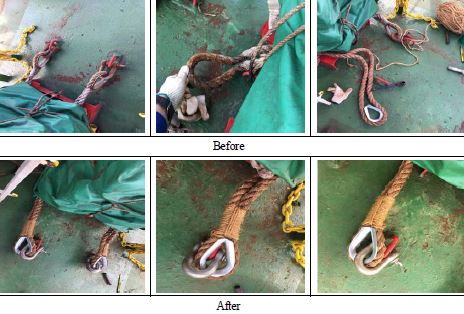
5.8 Embarkation ladder
Guide to Inspection
-
LSA CODE / CH VI / 6.1.
6.1.6 Embarkation ladders
6.1.6.1 Handholds shall be provided to ensure a safe passage from the deck to the head of the ladder and vice versa.
6.1.6.2 The steps of the ladder shall be:
.1 made of hardwood, free from knots or other irregularities, smoothly machined and free from sharp edges and splinters, or of suitable material of equivalent properties;
.2 provided with an efficient nonslip surface either by longitudinal grooving or by the application of an approved nonslip coating;
.3 not less than 480 mm long, 115 mm wide and 25 mm in depth, excluding any nonslip surface or coating; and
.4 equally spaced not less than 300 mm or more than 380 mm apart and secured in such a manner that they will remain horizontal.
6.1.6.3 The side ropes of the ladder shall consist of two uncovered manila ropes not less than 65 mm in circumference on each side. Each rope shall be continuous with no joints below the top step. Other materials may be used provided the dimensions, breaking strain, weathering, stretching and gripping properties are at least equivalent to those of manila rope. All rope ends shall be secured to prevent unravelling.
Check point
-
①Condition<br> - Rope, Shackle, Ladder steps
5.9 Drill, abandon ship (Mandatory)
Guide to inspection
-
SOLAS CH-III
Check Point
-
①Crew familiarity <br>Launch of the survival craft within a required time period<br>* preparation for embarking and launching by 2 crews in less than 5 min. (SOLAS III/13.1.3)<br>* Cargo ship : 10 min. for lifeboats and davit-launched liferafts (SOLAS III/31.1.5)
-
②Familiarization of the survival craft launching procedure (Commander, Substitute for commander and Bos’n)
-
③Drill evidence
-
③Drill evidence
-
④Instruction displayed
-
⑤Substitute
-
⑤Record keeping (Minimum req. SOLAS CH III,Reg.19)
5.10 Fire drill
Guide to Inspection
-
SOLAS / CH-III / Reg.19
SOLAS / CH-II-2 / Reg.15.2
3.5 Fire drills
3.5.1 Fire drills should be planned in such a way that due consideration is given to regular practice in the various emergencies that may occur depending on the type of ships and the cargo.
3.5.2 Each fire drill shall include;
.1 reporting to stations and preparing for the duties described in the muster list required by regulation 8;
.2 starting of a fire pump, using at least the two required jets of water to show that the system is in proper working order;
.3 checking of fireman's outfit and other personal rescue equipment;
.4 checking of relevant communication equipment;
.5 checking the operation of watertight doors, fire doors, fire dampers and main inlets and outlets of ventilation systems in the drill area;and
.6 checking the necessary arrangements for subsequent abandoning of the ship.
3.5.3 The equipment used during drills shall immediately be brought back to its fully operational condition and any faults and defects discovered during the drills shall be remedied as soon as possible.
Check Point
-
①Crew familiarity & Record keeping <br> (Minimum req. SOLAS CH III, Reg.19)
6. Inside of Accommodation (C/O, 3/O, 1/E)
6.1 Door with self-closing device
Guide to inspection
-
SOLAS / CH II-2 / Reg. 9.4.
** Self Closing Door shall be indicated on Fire Control Plan as A-60 (Eng. room Entrance
Door, Eng. Room floor emergency escape door, Galley door)
Check Point
-
①No holding Back
-
②Working (Fully closed)
-
③Visual condition (any damaged or hole)
6.2 Insulation
Guide to Inspection
-
SOLAS / CH II-2 / Reg. 4.3
4.3 Insulation surfaces protected against oil penetration
In spaces where penetration of oil products is possible, the surface of insulation shall be impervious to oil or oil vapours.
Check Point
-
①No missing / omission
-
②No breakaway
6.3 Fixed extinguisher system-CO2 (Rm)
Guide to Inspection
-
FSS / CH 5
2.1.3 System control requirements
2.1.3.1 The necessary pipes for conveying fire-extinguishing medium into the protected spaces shall be provided with control valves so marked as to indicate clearly the spaces to which the pipes are led. Suitable provisions shall be made to prevent inadvertent release of the medium into the space. Where a cargo space fitted with a gas fire-extinguishing system is used as a passenger space, the gas connection shall be blanked during such use. The pipes may pass through accommodations providing that they are of substantial thickness and that their tightness is verified with a pressure test, after their installation, at a pressure head not less than 5 N/mm². In addition, pipes passing through accommodation areas shall be joined only by welding and shall not be fitted with drains or other openings within such spaces. The pipes shall not pass through refrigerated spaces.
2.1.3.2 Means shall be provided for automatically giving audible and visual warning of the release of fire-extinguishing medium into any ro-ro spaces, container holds equipped with integral reefer containers, spaces accessible by doors or hatches, and other spaces in which personnel normally work or to which they have access. (Replaced by Res.MSC.339(91)) The audible alarms shall be located so as to be audible throughout the protected space with all machinery operating, and the alarms should be distinguished from other audible alarms by adjustment of sound pressure or sound patterns. The pre-discharge alarm shall be automatically activated (e.g., by opening of the release cabinet door). The alarm shall operate for the length of time needed to evacuate the space, but in no case less than 20 s before the medium is released. Conventional cargo spaces and small spaces (such as compressor rooms, paint lockers, etc.) with only a local release need not be provided with such an alarm.
Check Point
-
①Bottle contents, q'ty as per manufacturer's standard
-
②Hydro Test date
-
③Crew familiarity
-
④Insulation
-
⑤Safety pin location (As per manufacturer’s standard)
-
⑥Weight scale & accessories
-
⑦Flexible Connecting hose
-
⑧(If,fitted) condition of Ventilator
-
⑨Safety sign before entry
6.4 Fire control station
Guide to Inspection
-
SOLAS / CH II-2 & CH II-2, Reg.7 Detection and alarm
Check Point
-
①Fire detector Audible/Visible alarm test
-
②Water mist buzzer & Alarm test (if fitted)
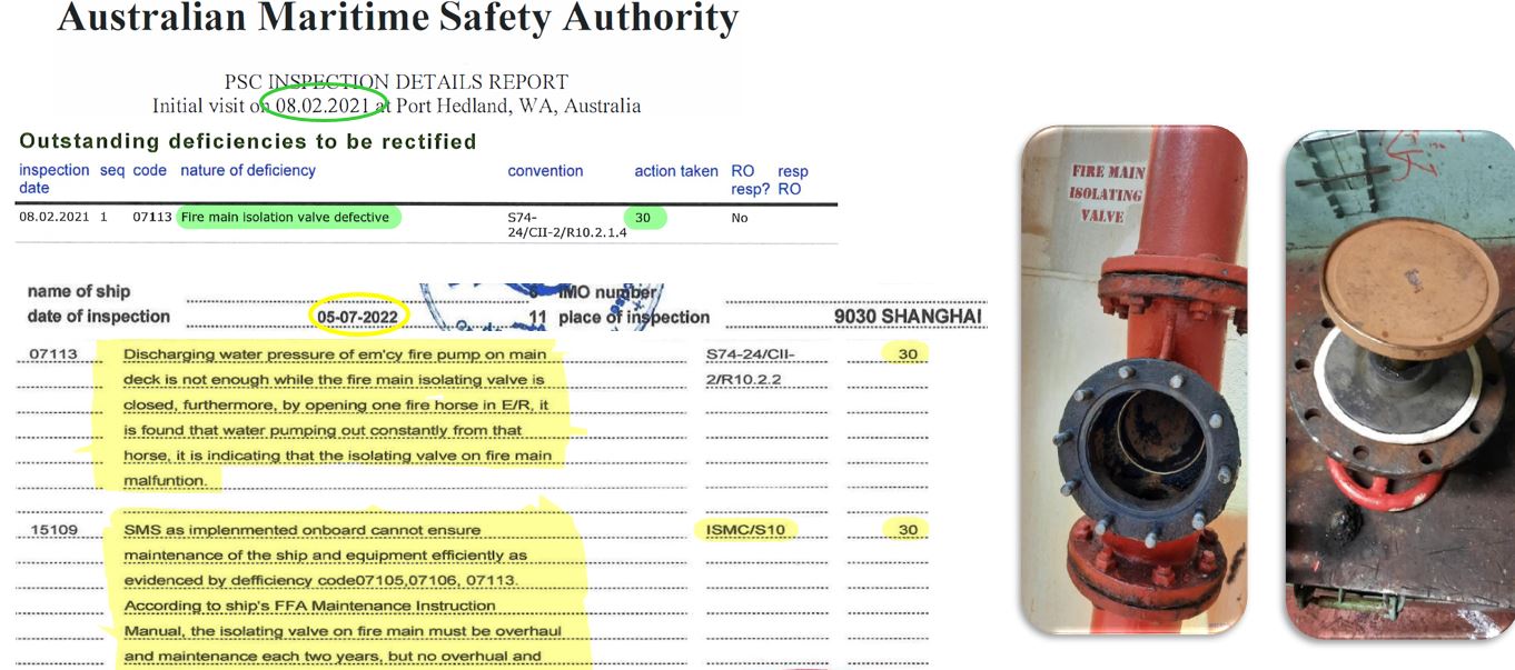
6.5 Isolating valve
Guide to Inspection
-
SOLAS / Ch II-2 / Reg. 10.2.1.1
Isolation valves shall be installed for all open deck fire main branches used for purposes other than fire fighting. In ships where deck cargo may be carried, the positions of the hydrants shall be such that they are always readily accessible and the pipes shall be arranged as far as practicable to avoid risk of damage by such cargo.
Check Point
-
①Location
-
②Condition of moving part
-
③Marking
6.6 Fire fighter's outfits
Guide to Inspection
-
FSS / CH 3 / 2.1
2.1 Fire-fighter's outfit
A fire-fighter's outfit shall consist of a set of personal equipment and a breathing apparatus.
2.1.1 Personal equipment
Personal equipment shall consist of the following:
.1 protective clothing of material to protect the skin from the heat radiating from the fire and from burns and scalding by steam. The outer surface shall be water-resistant;
.2 boots of rubber or other electrically non-conducting material;
.3 rigid helmet providing effective protection against impact;
.4 electric safety lamp (hand lantern) of an approved type with a minimum burning period of 3 hours. Electric safety lamps on tankers and those intended to be used in hazardous areas shall be of an explosion-proof type*; and
*Refer to the recommendations of International Electrotechnical Commission, in particular publication IEC 60079, Electrical Apparatus for Explosive Gas Atmosphere
.5 axe with a handle provided with high-voltage insulation.
2.1.2.1 Breathing apparatus shall be a self-contained compressed air breathing apparatus for which the volume of air contained in the cylinders shall be at least 1,200 l, or other self-contained breathing apparatus which shall be capable of functioning for at least 30 min. All air cylinders for breathing apparatus shall be interchangeable. (Replaced by Res.MSC.339(91))
2.1.2.2 Compressed air breathing apparatus shall be fitted with an audible alarm and a visual or other device which will alert the user before the volume of the air in the cylinder has been reduced to no less than 200 l.(Replaced by Res.MSC.339(91))
Refer to MSC.1/Circ.1499 UNIFIED INTERPRETATION OF CHAPTER 3 OF THE FSS CODE
2.1.3 Lifeline
For each breathing apparatus a fireproof lifeline of at least 30 m in length shall be provided. The lifeline shall successfully pass an approval test by statical load of 3.5 kN for 5 min without failure. The lifeline shall be capable of being attached by means of a snap-hook to the harness of the apparatus or to a separate belt in order to prevent the breathing apparatus becoming detached when the lifeline is operated.
Check Point
-
①Separate Stowage condition
-
②Bottle pressurized date & contents(incl. spare)
-
③Visual condition
-
④Belongings
-
⑤Emergency lights
-
⑥Two way VHF Communication
-
⑦B.A. Low pressure alarm
6.7 MLC-related matters
Check Point
-
①Clean and hygienic for Crew cabin
- bedding
- adequate artificial light
- hot and cold running water with showers -
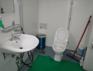
②Clean and available for the suitable public toilet
-
③Display the MLC Related certificate <br>- [Form] Checklist Maritime Labour Convention
6.8 Symbol
Guide to Inspection
-
SOLAS / CH II-2 / Reg.15.2.4<br>Res.A.952(23)<br>SOLAS / CH III / Reg. 9 Res.A.760(18)
Check Point
-
①Clear and highlight attached as per [Safety plan]
6.9 Hospital
Guide to Inspection
-
MLC, Reg.4.1 Medical care on board ship and ashore
The ship’s hospital shall not use the hospital as a cabin or storage space.
3. Each Member shall adopt laws and regulations establishing requirements for on-board hospital and medical care facilities and equipment and training on ships that fly its flag.
Check Point
-
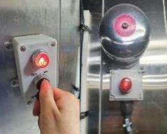
①Hospital call alarm (Sound, Visual)
-
②Medical log, Medicine list control
-
③Hygine condition
6.10 Ref.Chamber
Guide to Inspection
-
MLC, Reg.3.2 Food and catering
In accordance with the ongoing compliance procedures under Title 5, the competent authority shall require that frequent documented inspections be carried out on board ships, by or under the authority of the master, with respect to:
(a) supplies of food and drinking water in relation to their quantity, nutritional value, quality and variety;(Replaced by MLC 2022 Amendment)
(b) all spaces and equipment used for the storage and handling of food and drinking water; and
(c) galley and other equipment for the preparation and service of meals.
Check Point
-
①Ref.Chamber call alarm (Sound, Visual)
-
②Ref.Chamber Door frame(packing), door handle
-
③Temperature condition<br>- Chill 5°C & Freezer minus 18°C or colder"
-
④Exessive defrosting (Ice) on pipe
6.11 Cyber Security
Guide to Inspection
-
IMO Reg.MSC.428(98)
The cyber security management shall:
> Identify the roles and responsibilities of users, key personnel, and management both ashore and on board
> Identify the systems, assets, data and capabilities, which if disrupted, could pose risks to the ship’s operations and safety
> Implement technical measures to protect against a cyber-incident and ensure continuity of operations. This may include configuration of networks, access control to networks and systems, communication and boundary defence and the use of protection and detection software
> Implement activities and plans (procedural protection measures) to provide resilience against cyber incidents. This may include training and awareness, software maintenance, remote and local access, access privileges, use of removable media and equipment disposal
> Implement activities to prepare for and respond to cyber incidents.

Check Point
-
①Electric device security (Implement Procedure)
-
②Public PC Security(USB & Caution Sign)
-
③Cyber security training and drill implementation
7. Personal Life-saving appliances (C/O, 2/O)
7.1 Lifebuoys (Common)
Guide to Inspection
-
LSA / Ch 2.1
2.1.1 Lifebuoy specification
Every lifebuoy shall:
.1 have an outer diameter of not more than 800 mm and an inner diameter of not less than 400 mm;
.2 be constructed of inherently buoyant material; it shall not depend upon rushes, cork shavings or granulated cork, any other loose granulated material or any air compartment which depends on inflation for buoyancy;
.3 be capable of supporting not less than 14.5 kg of iron in fresh water for a period of 24 h;
.4 have a mass of not less than 2.5 kg;
.5 not sustain burning or continue melting after being totally enveloped in a fire for a period of 2 s;
.6 be constructed to withstand a drop into the water from the height at which it is stowed above the waterline in the lightest seagoing condition or 30 m, whichever is the greater, without impairing either its operating capability or that of its attached components;
.7 if it is intended to operate the quick release arrangement provided for the self-activated smoke signals and self-igniting lights, have a mass of not less than 4 kg (Amended by Res.MSC.207(81)); and
.8 be fitted with a grabline not less than 9.5 mm in diameter and not less than 4 times the outside diameter of the body of the buoy in length. The grabline shall be secured at four equidistant points around the circumference of the buoy to form four equal loops.
Check Point
-
①Weight <br>- Normal : not less than 2.5kg <br>- Self-activating smoke not more than 4kg
-
②Crack, Damage
-
③Marking (Ship name & Port of registry)
7.2 Quick release Life-buoy
Guide to Inspection
-
LSA / CH II / 2.1
.7 if it is intended to operate the quick release arrangement provided for the self-activated smoke signals and self-igniting lights, have a mass of not less than 4 kg (Amended by Res.MSC.207(81)); and
Check Point
-
①Quick Release
-
②Self-igniting light
-
③Expiration date
-
④Clear Marking
-
⑤Connection the link & Overall
7.3 Self-igniting light
Guide to Inspection
-
LSA / CH II / 2.1
2.1.2 Lifebuoy self-igniting lights
Self-igniting lights required by regulation III/7.1.3 shall:
.1 be such that they cannot be extinguished by water;
.2 be of white colour and capable of either burning continuously with a luminous intensity of not less than 2 cd in all directions of the upper hemisphere or flashing (discharge flashing) at a rate of not less than 50 flashes and not more than 70 flashes per min with at least the corresponding effective luminous intensity;
.3 be provided with a source of energy capable of meeting the requirement of paragraph 2.1.2.2 for a period of at least 2 h; and
.4 be capable of withstanding the drop test required by paragraph 2.1.1.6.
2.1.3 Lifebuoy self-activating smoke signals
Self-activating smoke signals required by regulation III/7.1.3 shall:
.1 emit smoke of a highly visible colour at a uniform rate for a period of at least 15 min when floating in calm water;
.2 not ignite explosively or emit any flame during the entire smoke emission time of the signal;
.3 not be swamped in a seaway;
.4 continue to emit smoke when fully submerged in water for a period of at least 10 s;
.5 be capable of withstanding the drop test required by paragraph 2.1.1.6; and
.6 be provided with a quick-release arrangement that will automatically release and activate the signal and associated self-igniting light connected to a lifebuoy having a mass of not more than 4 kg. ( Go! Added by Res.MSC.207(81))
Check Point
-
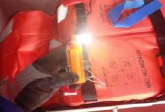
①Normal working & any damage (Bulb, Light cover)
-
②Battery expire date
7.4 Buoyant lifelines
Guide to Inspection
-
LSA / CH II / 2.1
2.1.4 Buoyant lifelines
Buoyant lifelines required by regulation III/7.1.2 shall:
.1 be non-kinking;
.2 have a diameter of not less than 8 mm; and
.3 have a breaking strength of not less than 5 kN.
Check Point
-
①Non-kinking.
-
②Not less than dia 8 mm dia & Strength 5 Kn
7.5 Lifejacket
Guide to Inspection
-
LSA / CH II / 2.2
2.2.1.5 An adult lifejacket shall be so constructed that:
.1 at least 75% of persons who are completely unfamiliar with the lifejacket can correctly don it within a period of 1 min without assistance, guidance or prior demonstration;
.2 after demonstration, all persons can correctly don it within a period of 1 min without assistance;
.3 it is clearly capable of being worn in only one way or inside-out and, if donned incorrectly, it is not injurious to the wearer;
.4 the method of securing the lifejacket to the wearer has quick and positive means of closure that do not require tying of knots;
.5 it is comfortable to wear; and
.6 it allows the wearer to jump into the water from a height of at least 4.5 m while holding on to the lifejacket, and from a height of at least 1m with arms held overhead, without injury and without dislodging or damaging the lifejacket or its attachments.
2.2.1.7 An adult lifejacket shall allow the person wearing it to swim a short distance and to board a survival craft.
2.2.1.11 A lifejacket shall have buoyancy which is not reduced by more than 5% after 24 h submersion in fresh water.
2.2.1.12 The buoyancy of a lifejacket shall not depend on the use of loose granulated materials.
2.2.1.13 Each lifejacket shall be provided with means of securing a lifejacket light as specified in paragraph 2.2.3 such that it shall be capable of complying with paragraphs 2.2.1.5.6 and 2.2.3.1.3.
2.2.1.14 Each lifejacket shall be fitted with a whistle firmly secured by a lanyard.
2.2.1.15 Lifejacket lights and whistles shall be selected and secured to the lifejacket in such a way that their performance in combination is not degraded.
2.2.1.16 A lifejacket shall be provided with a releasable buoyant line or other means to secure it to a lifejacket worn by another person in the water.
2.2.1.17 A lifejacket shall be provided with a suitable means to allow a rescuer to lift the wearer from the water into a survival craft or rescue boat.
2.2.3 Lifejacket lights
2.2.3.1 Each lifejacket light shall:
.1 have a luminous intensity of not less than 0.75 cd in all directions of the upper hemisphere;
.2 have a source of energy capable of providing a luminous intensity of 0.75 cd for a period of at least 8 h;
.3 be visible over as great a segment of the upper hemisphere as is practicable when attached to a lifejacket; and
.4 be of white colour.
2.2.3.2 If the light referred to in paragraph 2.2.3.1 is a flashing light, it shall, in addition:
.1 be provided with a manually operated switch; and
.2 flash at a rate of not less than 50 flashes and not more than 70 flashes per minute with an effective luminous intensity of at least 0.75 cd.”
Check Point
-
①Lighting, whistle
-
②Letter Marking & Appearance
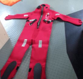
7.6 Immersion suit
Guide to Inspection
-
LSA / Ch 2.3
The Guidelines for monthly shipboard inspection of immersion suits and anti-exposure suits (MSC/Circ.1047) are very helpful in identifying obvious problems with a suit, but do not adequately address deterioration of seams and closures (zippers, etc.) which may not be readily apparent by visual inspection. Such deterioration can be detected by pressurization of the suit with air and testing the seams and closures for leaks with a soapy water solution.
2.3 Immersion suits
2.3.1 General requirements for immersion suits
2.3.1.1 An immersion suit shall be constructed with waterproof materials such that: ( Amended by Res.MSC.207(81))
.1 it can be unpacked and donned without assistance within 2 min, taking into account donning of any associated clothing*, donning of a lifejacket if the immersion suit must be worn in conjunction with a lifejacket to meet the requirements of paragraph 2.3.1.2, and inflation of orally inflatable chambers if fitted; ( Replaced by Res.MSC.207(81))
* Refer to paragraph 3.1.3 of the Recommendation on testing of life-saving appliances, adopted by the Maritime Safety Committee of the Organization by resolution MSC.81(70) , as amended.
.2 it will not sustain burning or continue melting after being totally enveloped in a fire for a period of 2 s;
.3 it will cover the whole body with the exception of the face, except that covering for the hands may be provided by separate gloves which shall be permanently attached to the suit; ( Replaced by Res.MSC.207(81))
.4 it is provided with arrangements to minimize or reduce free air in the legs of the suit; and
.5 following a jump from a height of not less than 4.5 m into the water there is no undue ingress of water into the suit.
2.3.1.2 An immersion suit on its own, or worn in conjunction with a lifejacket if necessary, shall have sufficient buoyancy and stability in calm fresh water to: ( Replaced byRes.MSC.207(81))
.1 lift the mouth of an exhausted or unconscious person clear of the water by not less than 120 mm; and ( Replaced by Res.MSC.207(81))
.2 allow the wearer to turn from a face-down to a face-up position in not more than 5 s. ( Replaced by Res.MSC.207(81))
2.3.1.3 An immersion suit shall permit the person wearing it, and also wearing a lifejacket if the immersion suit is to be worn in conjunction with a lifejacket, to:
.1 climb up and down a vertical ladder at least 5 m in length;
.2 perform normal duties associated with abandonment;
.3 jump from a height of not less than 4.5 m into the water without damaging or dislodging the immersion suit or its attachments, or being injured; and ( Amended by Res.MSC.207(81))
.4 swim a short distance through the water and board a survival craft.
Check Point
-
①Condition (glue/zipper/sewing parts, detached or sticked, etc)
-
②Light & whishle condition
8. Main Deck & Cargo Hold(Bulk Carrier and General Dry Cargo Ship) (C/O)
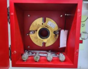
8.1 International shore connection
Guide to Inspection
-
SOLAS / Ch II-2 10.2.1.7 / MSC.98(73)"
The international shore connection is a standard sized flange with nuts, bolts and washers and a coupling for ship’s fittings.
The fitting and joining must be suitable for a working pressure of 10.5 bar. Four bolts are required of 16mm diameter and 50mm length, also eight washers and a gasket of any suitable material.
Check Point
-
①Retaining with required items - Bolt 16mm, 4 pcs with 50mm length - Nut 16mm, 4 pcs - Spanner
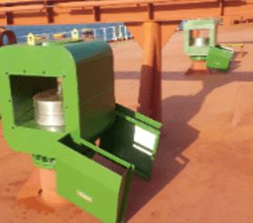
8.2 Ventilator
Guide to Inspection
-
ICLL Annex I / Chapter II / Reg. 19
(1) Ventilators in position 1 or 2 to spaces below freeboard decks or decks of enclosed superstructures shall have coamings of steel or other equivalent material, substantially constructed and efficiently connected to the deck. Where the coaming of any ventilator exceeds 900 millimetres 35½ ( inches) in height it shall be specially supported.
(2) Ventilators passing through superstructures other than enclosed superstructures shall have substantially constructed coamings of steel or other equivalent material at the freeboard deck.
(3) Ventilators in position 1 the coamings of which extend to more than 4.5 m (14.8 feet) above the deck, and in position 2 the coamings of which extend to more than 2.3 m (7.5 feet) above the deck, need not be fitted with closing arrangements unless specifically required by the Administration. IACS UI LL 58
(4) Except as provided in paragraph (3) of this Regulation ventilator openings shall be provided with efficient weathertight closing appliances. In ships of not more than 100 m (328 feet) in length the closing appliances shall be permanently attached; where not so provided in other ships, they shall be conveniently stowed near the ventilators to which they are to be fitted. Ventilators in position 1 shall have coamings of a height of at least 900 millimetres ( 35½ inches) above the deck; in position 2 the coamings shall be of a height at least 760 millimetres (30 inches) above the deck. IACS UI LL 52 and LL 58
Check Point
-
①Damper moving/corrosion (Free-up)
-
②Coaming
-
③Vent cover
-
④Inside inspection hole (if fitted)
-
8.3 Air pipe (Vent)
Guide to Inspection
-
ICLL Annex I / Chapter II / Reg. 20
Where air pipes to ballast and other tanks extend above the freeboard or superstructure decks, the exposed parts of the pipes shall be of substantial construction; the height from the deck to the point where water may have access below shall be at least 760 mm (30 inches) on the freeboard deck and 450 millimetres ( 17½ inches) on the superstructure deck. Where these heights may interfere with the working of the ship, a lower height may be approved, provided the Administration is satisfied that the closing arrangements and other circumstances justify a lower height. Satisfactory means permanently attached, shall be provided for closing the openings of the air pipes.
Check Point
-
①Any missing of sounding cap
-
②Floating Ball or floater condition and Rubber packing condition
-
③Marking
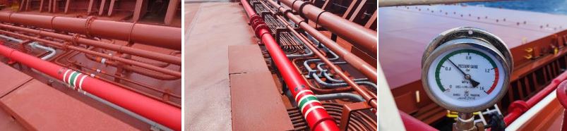
8.4 Fire main line
Guide to Inspection
-
SOLAS / Ch II-2 / Reg.10.2. Water supply
2.1.6 Pressure at hydrants
With the two pumps simultaneously delivering water through the nozzles specified in paragraph 2.3.3, with the quantity of water as specified in paragraph 2.1.3, through any adjacent hydrants, the following minimum pressures shall be maintained at all hydrants:
.2 for cargo ships,
6,000 gross tonnage and upwards 0.27 N/mm²
less than 6,000 gross tonnage; 0.25 N/mm² and
.3 the maximum pressure at any hydrant shall not exceed that at which the effective control of a fire hose can be demonstrated.
Check Point
-
①Hole or any leakage (Normal pressure during Anchor wash)
-
②Corrosion
-
③Valve moving
-
④Patching (Any doubling)
8.5 Main deck
-
①Corrosion/hole
-
②No crack
-
③Paint condition
8.6 Small hatch
Guide to Inspection
-
ICLL Annex I / Chapter II / Reg. 18
(1) Manholes and flush scuttles in position 1 or 2 or within superstructures other than enclosed superstructures shall be closed by substantial covers capable of being made watertight. Unless secured by closely spaced bolts, the covers shall be permanently attached.
(2) Openings in freeboard decks other than hatchways, machinery space openings, manholes and flush scuttles shall be protected by an enclosed superstructure, or by a deckhouse or companionway of equivalent strength and weathertightness. Any such opening in an exposed superstructure or in the top of a deckhouse on the freeboard deck which gives access to a space below the freeboard deck or a space within an enclosed superstructure shall be protected by an efficient deckhouse or companionway. Doorways in such deckhouses or companionways shall be fitted with doors complying with the requirements of Regulation 12 (1).
IACS UI LL 46
Check Point
-
① Weathertight (Packing, cover frame deformation)
-
② Closing Device (Dog bolt free-up)
-
③ Corrosion and hole: Visual and hammer test
-
④ Packing : dropping and damage
-
⑤ ETC: Marking, Coaming Corrosion and hole
8.7 Hatch cover
Guide to Inspection
-
ICLL, Annex I, Ch-II, Reg.16
Hatchway Coamings
(1) At positions 1 and 2 the height above the deck of hatchway coamings fitted with weathertight hatch covers of steel or other equivalent material fitted with gaskets and clamping devices shall be as specified in Regulation 15(1). The height of these coamings may be reduced, or the coamings omitted entirely, on condition that the Administration is satisfied that the safety of the ship is not thereby impaired in any sea conditions. Where coamings are provided they shall be of substantial construction.
Weathertight Covers
(2) Where weathertight covers are of mild steel the strength shall be calculated with assumed loads not less than 1.75 metric tons per square metre (358 pounds per square foot) on hatchways in position 1, and not less than 1.30 metric tons per square metre (266 pounds per square foot) on hatchways in position 2, and the product of the maximum stress thus calculated and the factor of 4.25 shall not exceed the minimum ultimate strength of the material. They shall be so designed as to limit the deflection to not more than 0.0028 times the span under these loads. Mild steel plating forming the tops of covers shall be not less in thickness than one per cent of the spacing of stiffeners or 6 millimetres (0.24 inches) if that be greater. The provisions of Regulation 15(5) are applicable for ships of not more than 100 metres (328 feet) in length.
(3) The strength and stiffness of covers made of materials other than mild steel shall be equivalent to those of mild steel to the satisfaction of the Administration.
Check Point
-
①Corrosion/hole
-
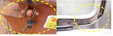
②Packing (Deform and damage)
-
③Weathertightness - Hose Test, Water pressure
8.8 Hatch coaming, stay, stiffener
Guide to Inspection
-
ICLL / Annex I / Chapter II / Reg. 16
Means for Securing Weathertightness
(4) The means for securing and maintaining weathertightness shall be to the satisfaction of the Administration. The arrangements shall ensure that the tightness can be maintained in any sea conditions, and for this purpose tests for tightness shall be required at the initial survey, and may be required at periodical surveys and at annual inspections or at more frequent intervals.
The following parameters can be used for a hose test: Water pressure 2 bar, Nozzle size 15 - 18 mm, Spraying distance 1 - 1.5 m.
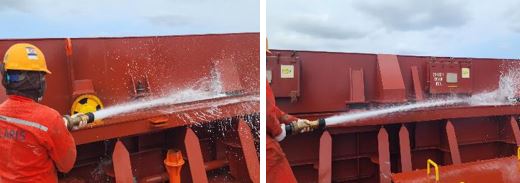
Check Point
-
①Corrosion and hole (Visual and hammer test)
-
②Crack (End stay, bracket)
8.9 Bulwark and handrail
Guide to Inspection
-
ICLL / Annex I / Chapter II / Reg. 25
According to paragraph 2 of Regulation 25 “Protection of the Crew” in Annex I of the Load Line Convention, guard rails must be installed around all exposed decks and must be at least one meter in height from the deck. Chains installed between two fixed stanchions and/or bulwarks are allowed in lieu of guard rails where necessary for the ship’s normal operation.
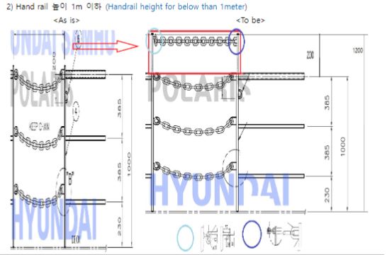
Check Point
-
①Corrosion and hole (Visual and hammer test)
-
②Crack (End stay, bracket)
8.10 Cleats for hatch cover
Guide to Inspection
-
ICLL Annex I / Chapter II / Reg. 16
Quick acting cleats should be fitted at their original positions free of any corrosion or bending. The rubber washers that are fitted to the cleats should have proper elasticity. Other component parts to which cleats are welded or acting on such as coaming table, crutches, snugs, panel side plating should be in good condition.
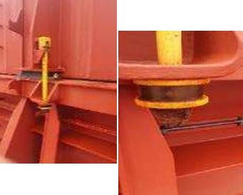
Check Point
-
①Corrosion and hole(Visual and hammer test)
-
②Socket (Regular Free-up)
-
③Gap Check
8.11 Cargo holds – Overall survey
Guide to Inspection
-
SOLAS CH-XII-Reg.7
After every discharge and each cleaning, holds should be formally inspected by the Master or Chief Officer. The ballast tanks, void spaces, cofferdams, and duct keel should be inspected at least annually. Ballast tanks and void spaces adjacent to grab or bulldozer’s damage shall be inspected after completion of the discharge. This inspection should be recorded with photographs.
The inspection plan and records should at least cover the following:
> Framing of the holds – damaged and ‘tripped’ brackets
> Condition of bulkhead coatings on the holds
> Condition of hatch covers, trackways, compression bars, channel drainage, hatch rubbers, cross, hatch drain valve and side cleats
> Hatch and hold vents and watertight lids, including access hatch lids, rubber packing and closing cleats and dogs
> Tank top, any damage
> Condition of coating in ballast tanks, void space, cofferdam, and duct keel
> Condition of tank top double bottom or side tank access lid, condition and the fitting of the gaskets, condition of nuts
> Condition of hold ladders, platforms and handrails
> Condition of hold piping, air vent and water ballast sounding lines, and piping protection brackets
> Condition of bilge wells, including bilge covers, strum boxes, and bilge well valves, including non-return valves
> Condition of bilge high-level alarms
> Condition of lights and light fittings.
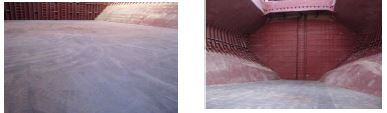
Check Point
-
① Corrosion and crack (ex) substructure of cross deck)
-
② Leakage (Crack and flood by Ballast water)
-
③ Ship’s Repair (Re-welding or Double plate)<br>** Ship’s repair shall be reported to classification or administration(SOLAS Ch.I/Reg.11(c))
-
④Corner plate (Heavy Stress part - Crack)
8.12 Deck scupper
Guide to Inspection
-
SOLAS / CH II-1 / Reg. 35-1 2.6.1
Scuppers should be plugged during bunkering and some dirty dry bulk cargo operation. Scupper filters should be used when draining rainwater during loading/discharging dirty dry bulk cargoes.
2.6 Provision shall be made for the drainage of enclosed cargo spaces situated on the bulkhead deck of a passenger ship and on the freeboard deck of a cargo ship, provided that the Administration may permit the means of drainage to be dispensed with in any particular compartment of any ship or class of ship if it is satisfied that by reason of size or internal subdivision of those spaces the safety of the ship is not thereby impaired.
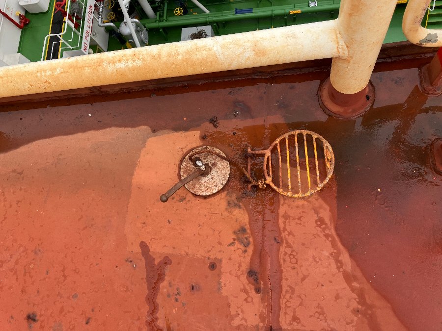
Check Point
-
①Scupper watertight condition
8.13 Mooring winch & Windlass (Fore & Aft)
Guide to Inspection
-
SOLAS / CH II-1 / Reg. 3-8
MSC.1 / Circ 1662
MSC.1 / Circ 1619/1620
For all ships, mooring equipment, including lines, shall be inspected and maintained in a suitable condition for their intended purposes.
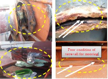
Check Point
-
①Hyd pipe & flange Leak
-
②Hyd.pump side clean condition (fore/aft)
-
③Winch Brake condition
-
④Hyd.pump pressure & Ampere Gauge condition
-
⑤Clutch movable
-
⑥Cooler cleaning (Within 1 Year)
-
⑦Hyd.pump coupling condition
-
⑧Non-slip (Paint, plate etc)
8.14 Mooring Equipment
Guide to Inspection
-
SOLAS / CH II-1 / Reg. 3-8
MSC.1 / Circ 1619/1620

Check Point
-
①Corrosion and crack<br>- Fairleader, bitt/bollard, Chock, Warping drum etc
-
②Movable and working fairleader roller
-
③Mooring rope <br> - Tails, Stopper, messenger, heaving line etc
-
④Marking
8.15 Accommodation ladder
Guide to Inspection
-
SOLAS / CH II-1 / Reg. 3-9
MSC.1 / Circ 1331
The use of a short brow gangway attached to the bottom platform of an accommodation ladder, should be identified as a highrisk task and specific permit and risk assessment for such task should be available onboard.
SOLAS Chapter II-1 Regulation 3 9 and MSC. 1/ Circ.1331 include requirements for safely rigging vessel access equipment.
> Gangways should not be used at an angle of inclination greater than 30 degrees from the horizontal.
> Ship accommodation ladders should not be used at angles greater than 55 degrees from the horizontal, unless designed and constructed for use at angles greater than these and marked as such.
> Adequate lighting, lifebuoys and a mounted safety net sufficient to prevent falls must be provided.
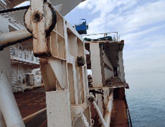
Check Point
-
①Maintenance condition (Take a overall photo) - Damage of Steps, handrails - Moving of Turntable - Air motor operate - Wire condition (Last replaced date) - Greasing condition etc)
-
②Safety net
-
③Safety sign and marking
-
④Secondary rope (fall prevention)
-
⑤Proper illumination
8.16 Pilot ladder (Include Reel)
Guide to Inspection
-
SOLAS / CH V / Reg.23 & Res A / 1045(27)
Expected service life of the pilot ladder, which may be less than 30 months, especially on ladders with mechanically placed metal clamps that prevent inspection of the side ropes. If a pilot ladder’s service life exceeds 30 months, the test specified in section 6.6 of ISO standard 799-2021 should be conducted.
All pilot ladders used for pilot transfer shall be clearly identified with tags or other permanent marking so as to enable identification of each appliance for the purposes of survey, inspection and record keeping. A record shall be kept on the ship as to the date the identified ladder is placed into service and any repairs effected.
The top of the pilot ladder should be secured to the certified fixing point and not to handrails. Ladder steps or spacers should not be rigged in a position in which they are taking the weight of the ladder.
The easiest way to secure the ladder is the use of two strong (at least 2 x 24 kN) manila ropes directly attached to each side rope of the pilot ladder, by means of a rolling hitch knot.
Any pilot ladders not in use should be clearly identified and tagged.
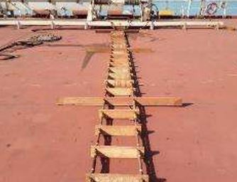
Check Point
-
①Any damage (Take a overall photo)
-
②Certificate Tag & Keep Cert.
-
③Validity period (Ladder : 30M, Man Rope : 12M)<br>- Based on manufacture date for Ladder and Man Rope
-
④Crew familiarty (Risk, Rolling hitch)
-
⑤Proper illumination
8.17 Paint Store
Guide to Inspection
-
SOLAS CH II-1 / Reg. 45
SOLAS CH II-2 / Reg. 10.6.3
6.3 Spaces containing flammable liquid
6.3.1 Paint lockers shall be protected by:
.1 a carbon dioxide system, designed to give a minimum volume of free gas equal to 40% of the gross volume of the protected space;
.2 a dry powder system, designed for at least 0.5 kg powder/m³ ;
.3 a water spraying or sprinkler system, designed for 5 litres/m² min. Water spraying systems may be connected to the fire main of the ship; or
.4 a system providing equivalent protection, as determined by the Administration.
In any case, the system shall be operable from outside the protected space.
6.3.2 Flammable liquid lockers shall be protected by an appropriate fire-extinguishing arrangement approved by the Administration.
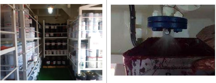
Check Point
-
①Fire extinguisher
-
②Explosion-proof light
-
③Ventilator
-
④nozzle angle (Not blocking by obstruction)
-
⑤Sprinkler Test
8.18 Hull Condition
Guide to Inspection
-
SOLAS XI-1,Reg.3.5.1, ICLL Annex-1,Reg.8
The ring, lines and letters shall be painted in white or yellow on a dark ground or in black on a light ground. They shall also be permanently marked on the sides of the ships to the satisfaction of the Administration. The marks shall be plainly visible and, if necessary, special arrangements shall be made for this purpose.
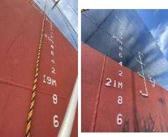
Check Point
-
①Draft marking(6 Point) & Plimsoll marking (Last available photo)
-
②Damage or Dent
9. Forecastle deck, Bosun Store (C/O & 2/O)
9.1 Bosun store Ventilator
Guide to Inspection
-
SOLAS / Ch II-2 / Reg. 5.2.1.2
2 Control of air supply and flammable liquid to the space
2.1 Closing appliances and stopping devices of ventilation
2.1.1 The main inlets and outlets of all ventilation systems shall be capable of being closed from outside the spaces being ventilated. The means of closing shall be easily accessible as well as prominently and permanently marked and shall indicate whether the shutoff is open or closed.
2.1.2 Power ventilation of accommodation spaces, service spaces, cargo spaces, control stations and machinery spaces shall be capable of being stopped from an easily accessible position outside the space being served. This position shall not be readily cut off in the event of a fire in the spaces served.
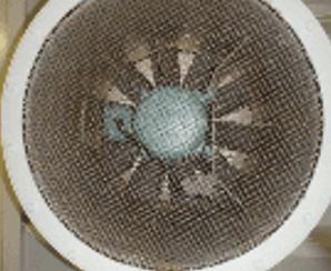
Check Point
-
①Damper moving/corrosion
-
②Marking
-
③Normal Operation
9.2 Small hatch
Guide to Inspection
-
ICLL Annex I / Chapter II / Reg. 18
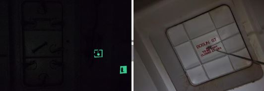
Check Point
-
①Weathertight (No Light from Bosun store)
-
②Closing Device
-
③Corrosion/hole
-
④Packing
9.3 Navigational lights & Lighting system
Guide to Inspection
-
COLREG / Part C / Part D
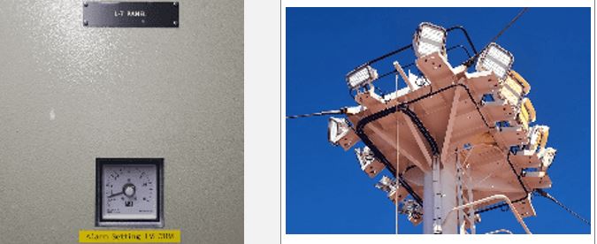
Check Point
-
①Required angle
-
②Any Covered by painting or damage/broken
-
③Check Earth (During turn on the lights)
-
④Illumination for the Mooring area
9.4 Dewatering System
Guide to Inspection
-
SOLAS 2006 Amend / Chapter XII / Reg. 12
SOLAS CH II-1 / Reg.12
.2 in any ballast tank forward of the collision bulkhead required by regulation II-1/12, giving an audible and visual alarm when the liquid in the tank reaches a level not exceeding 10% of the tank capacity. An alarm overriding device may be installed to be activated when the tank is in use; and(Replaced by Res.MSC.216(82)),
.3 in any dry or void space other than a chain cable locker, any part of which extends forward of the foremost cargo hold, giving an audible and visual alarm at a water level of 0.1 m above the deck. Such alarms need not be provided in enclosed spaces the volume of which does not exceed 0.1% of the ship's maximum displacement volume.
2 The audible and visual alarms specified in paragraph 1 shall be located on the navigation bridge.
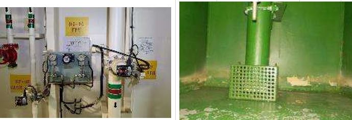
Check Point
-
①Remote control V/V working
-
②Sensor working
-
③Suction
9.5 Anchor Pipe
Guide to Inspection
-
① Bosun Store (inside) Anchor Washing Pipe corrosion and damage
② Air pipe for F.P.T : corrosion and hole
③ Bosun store equipment lashing and cleanness
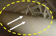
Check Point
-
①Corrosion/hole(trace of leaking)
9.6 Chian Locker wall
Guide to Inspection
-
Reg. 22-2, ICLL 1966 & 1988 Protocol as amended
Spurling pipes and cable lockers shall be watertight up to the deck exposed to weather.
IACS UR L4
It is to be closed by a substantial cover and secured by closely spaced bolts. Butterfly nuts and/or hinged bolts are prohibited as the securing mechanism for the access cover.
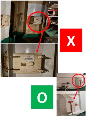
Check Point
-
①Corrosion/hole
9.7 F’cle deck/ Weather tight door/Wall
Guide to Inspection
-
ICLL / ANNEX I / Reg. 12
(1) All access openings in bulkheads at ends of enclosed superstructures shall be fitted with doors of steel or other equivalent material, permanently and strongly attached to the bulkhead, and framed, stiffened and fitted so that the whole structure is of equivalent strength to the unpierced bulkhead and weathertight when closed. The means for securing these doors weathertight shall consist of gaskets and clamping devices or other equivalent means and shall be permanently attached to the bulkhead or to the doors themselves, and the doors shall be so arranged that they can be operated from both sides of the bulkhead.
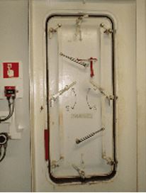
Check Point
-
①No penetrating light from outside Bosun store and small hatch
9.8 Lifesaving
Guide to Inspection
-
SOLAS CH-III / Reg.11.4
SOLAS CH-III/ Reg.13
Survival craft muster and embarkation arrangements
4 Muster and embarkation stations shall be adequately illuminated by lighting supplied from the emergency source of electrical power required by regulation II-1/42 or II-1/43, as appropriate.
Stowage of survival craft
1 Each survival craft shall be stowed :
.1 so that neither the survival craft nor its stowage arrangements will interfere with the operation of any other survival craft or rescue boat at any other launching station;
.2 as near the water surface as is safe and practicable and, in the case of a survival craft other than an liferaft intended for throw over board launching, in such a position that the survival craft in the embarkation position is not less than 2 m above the waterline with the ship in the fully loaded condition under unfavourable conditions of trim of up to 10°and listed up to 20°either way, or to the angle at which the ship's weather deck edge becomes submerged, whichever is less;
.3 in a state of continuous readiness so that two crew members can carry out preparations for embarkation and launching in less than 5 min;
Refer to IACS UI SC213
.4 fully equipped as required by this chapter and the Code;and
.5 as far as practicable, in a secure and sheltered position and protected from damage by fire and explosion. In particular, survival craft on tankers, other than the liferafts required by regulation 31.1.4, shall not be stowed on or above a cargo tank, slop tank, or other tank containing explosive or hazardous cargoes.
2 Lifeboats for lowering down the ship's side shall be stowed as far forward of the propeller as practicable. On cargo ships of 80 m in length and upwards but less than 120 m in length, each lifeboat shall be so stowed that the after end of the lifeboat is not less than the length of the lifeboat forward of the propeller. On cargo ships of 120 m in length and upwards and passenger ships of 80 m in length and upwards, each lifeboat shall be so stowed that the after end of the lifeboat is not less than 1.5 times the length of the lifeboat forward of the propeller. Where appropriate, the ship shall be so arranged that lifeboats, in their stowed positions, are protected from damage by heavy seas.
3 Lifeboats shall be stowed attached to launching appliances.
4.1 Every liferaft shall be stowed with its painter permanently attached to the ship.
4.2 Each liferaft or group of liferafts shall be stowed with a float-free arrangement complying with the requirements of paragraph 4.1.6 of the Code so that each floats free and, if inflatable, inflates automatically when the ship sinks.
4.3 Liferafts shall be so stowed as to permit manual release of one raft or container at a time from their securing arrangements.
4.4 Paragraphs 4.1 and 4.2 do not apply to liferafts required by regulation 31.1.4.
5 Davit-launched liferafts shall be stowed within reach of the lifting hooks, unless some means of transfer is provided which is not rendered inoperable within the limits of trim and list prescribed in paragraph 1.2 or by ship motion or power failure.
6 Liferafts intended for throw-overboard launching shall be so stowed as to be readily transferable for launching on either side of the ship unless liferafts, of the aggregate capacity required by regulation 31.1 to be capable of being launched on either side, are stowed on each side of the ship.
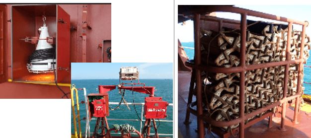
Check Point
-
①Liferaft re-setting condition
-
②Liferaft instruction
-
③Emergency light test
-
④Embarkation Ladder condition - Rope, Shackle, Ladder steps
-
⑤Lifejacket, Immersion suit
9.9 Anchor Emergency release
Guide to Inspection
-
MSC.1 / Circ 1662
3.1.7 Emergency release
3.1.7.1 Anchor handling winches should be designed to facilitate emergency release of the load on the wire in a safe and controlled manner, both under normal as well as dead-ship conditions.
3.1.7.2 The controls for actuation of the emergency release should be placed at the main control station. Emergency release function may also be available at the local control station.
3.1.7.3 Emergency release control should be protected against unintentional activation.
3.1.7.4 The design and operation of the emergency release should take into consideration
restrictions on the pay-out speed of the wire due to inertia and any restrictions due to onboard arrangements.
3.1.7.5 Instructions for the operation of the emergency release should be clearly displayed at the navigation bridge and locally at the winch.
3.1.7.6 After an emergency release, the complete anchor handling winch system should be inspected for signs of damage or deterioration. Any identified damage or deterioration should be rectified before the anchor handling winch is put back into service.
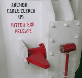
Check Point
-
①No obstruction for use bitter end
-
②Clear marking bitter end (Take a overall)
10. Poop Deck (C/O)
10.1 Navigational lights & Lighting system
Guide to Inspection
-
COLREG / Part C / Part D
(a) 'Masthead light' means a white light placed over the fore and aft centerline of the vessel showing an unbroken light over an arc of the horizon of 225 degrees and so fixed as to show the light from right ahead to 22.5 degrees abaft the beam on either side of the vessel.
(b) 'Sidelights' means a green light on the starboard side and a red light on the port side each showing an unbroken light over an arc of the horizon of 112.5 degrees and so fixed as to show the light from right ahead to 22.5 degrees abaft the beam on its respective side. In a vessel of less than 20 meters in length the sidelights may be combined in one lantern carried on the fore and aft centreline of the vessel.
(c) 'Sternlight' means a white light placed as nearly as practicable at the stern showing an unbroken light over an arc of the horizon of 135 degrees and so fixed as to show the light 67.5 degrees from right aft on each side of the vessel.
(d) 'Towing light' means a yellow light having the same characteristics as the 'sternlight' defined in paragraph(c) of this Rule.
(e) 'All round light' means a light showing an unbroken light over an arc of the horizon of 360 degrees.
(f) 'Flashing light' means a light flashing at regular intervals at a frequency of 120 flashes or more per minute.
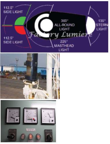
Check Point
-
①Required angle
-
②Any Covered by painting or damage/broken
-
③Check Earth (During turn on the lights)
-
④Illumination for the Mooring area
10.2 Air pipe & Sounding
Guide to Inspection
-
ICLL Annex I / Chapter II / Reg. 20
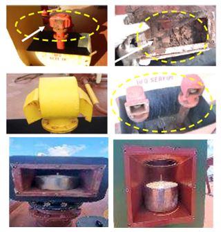
Check Point
-
①Marking
-
②Air pipe head, ball, floater damage
-
③Any missing of sounding cap
10.3 Small Hatch (ICLL Annex I / Chapter II / Reg. 18)
-
①Weathertight
-
②Closing Device
-
③Corrosion/hole
-
④Packing
10.4 Access control
-
①Secuirty seal (S/G RM), No padlock from outside
11. Steering gear room & Em’cy fire pump room (Engineers, 2/O)
11.1 Em’cy lighting
Guide to Inspection
-
SOLAS / CH-II-1 / Reg.43
2 The electrical power available shall be sufficient to supply all those services that are essential for safety in an emergency, due regard being paid to such services as may have to be operated simultaneously. The emergency source of electrical power shall be capable, having regard to starting currents and the transitory nature of certain loads, of supplying simultaneously at least the following services for the periods specified hereinafter, if they depend upon an electrical source for their operation :
2.1 For a period of 3 h, emergency lighting at every muster and embarkation station and over the sides as required by regulations III/11.4 and III/16.7.
2.2 For a period of 18 h, emergency lighting :
.1 in all service and accommodation alleyways, stairways and exits, personnel lift cars and personnel lift trunks ;
.2 in the machinery spaces and main generating stations including their control positions ;
.3 in all control stations, machinery control rooms, and at each main and emergency switchboard ;
.4 at all stowage positions for firemen's outfits ;
.5 at the steering gear ;
.6 at the fire pump referred to in paragraph 2.5, at the sprinkler pump, if any, and at the emergency bilge pump, if any, and at the starting positions of their motors ; and
.7 in all cargo pump-rooms of tankers constructed on or after 1 July 2002.
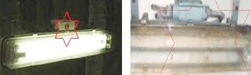
Check Point
-
①Operating Test
-
②No damage
11.2 Em'cy communication
Guide to Inspection
-
SOLAS / CH II-1 / Reg 29.10
10 A means of communication shall be provided between the navigating bridge and the steering gear compartment.
SOLAS / CH-V / Reg. 19.2.1.
.9 a telephone, or other means, to communicate heading information to the emergency steering position, if provided.
Check Point
-
①S/G room, em’cy telephone operation
11.3 Gyro repeater
Guide to Inspection
-
SOLAS / Ch V / Reg.19
2 Shipborne navigational equipment and systems
2.1 All ships irrespective of size shall have:
.1 a properly adjusted standard magnetic compass, or other means, independent of any power supply to determine the ship's heading and display the reading at the main steering position;
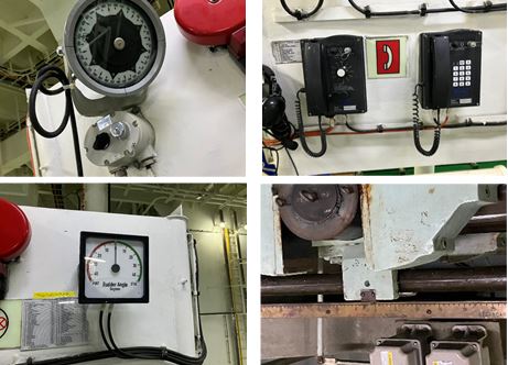
Check Point
-
①Synchronize with Bridge
-
②Light, indicator
11.4 Steering Gear
Guide to Inspection
-
SOLAS / CH II-1 / Reg 29
1 Unless expressly provided otherwise, every ship shall be provided with a main steering gear and an auxiliary steering gear to the satisfaction of the Administration. The main steering gear and the auxiliary steering gear shall be so arranged that the failure of one of them will not render the other one inoperative.
10 A means of communication shall be provided between the navigating bridge and the steering gear compartment.
11 The angular position of the rudder shall:
.1 if the main steering gear is power operated, be indicated on the navigating bridge. The rudder angle indication shall be independent of the steering gear control system;
.2 be recognizable in the steering gear compartment.
12 Hydraulic power-operated steering gear shall be provided with the following:
.1 arrangements to maintain the cleanliness of the hydraulic fluid taking into consideration the type and design of the hydraulic system;
.2 a low level alarm for each hydraulic fluid reservoir to give the earliest practicable indication of hydraulic fluid leakage. Audible and visual alarms shall be given on the navigating bridge and in the machinery space where they can be readily observed; and
.3 a fixed storage tank having sufficient capacity to recharge at least one power actuating system including the reservoir, where the main steering gear is required to be power operated. The storage tank shall be permanently connected by piping in such a manner that the hydraulic systems can be readily recharged from a position within the steering gear compartment and shall be provided with a contents gauge.
13 The steering gear compartment shall be:
.1 readily accessible and, as far as practicable, separated from machinery spaces; and
.2 provided with suitable arrangements to ensure working access to steering gear machinery and controls. These arrangements shall include handrails and gratings or other non-slip surfaces to ensure suitable working conditions in the event of hydraulic fluid leakage.
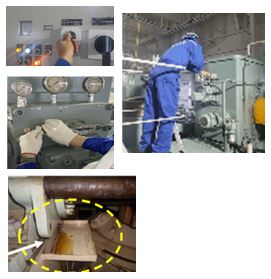
Check Point
-
①Oil leakage
-
②L.O tank & alarm for Hyd. pump
-
③Em’cy steering
-
④Automatic start-up after loss of primary
-
⑤Rudder indicator clear marking
-
⑥Level of L.O.
11.5 Steering gear room Fan
Guide to Inspection
-
SOLAS / CH II-1 / Reg 35
Machinery spaces of category A shall be adequately ventilated so as to ensure that when machinery or boilers therein are operating at full power in all weather conditions including heavy weather, an adequate supply of air is maintained to the spaces for the safety and comfort of personnel and the operation of the machinery. Any other machinery space shall be adequately ventilated appropriate for the purpose of that machinery space.
Check Point
-
①Working
-
②Low insulation mat
11.6 Electric Panel
Guide to Inspection
-
SOLAS / CH II-1 / Reg 45
2 Main and emergency switchboards shall be so arranged as to give easy access as may be needed to apparatus and equipment, without danger to personnel. The sides and the rear and, where necessary, the front of switchboards shall be suitably guarded. Exposed live parts having voltages to earth exceeding a voltage to be specified by the Administration shall not be installed on the front of such switchboards. Where necessary, nonconducting mats or gratings shall be provided at the front and rear of the switchboard.
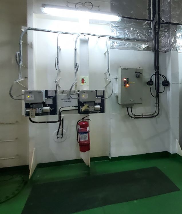
Check Point
-
①Low insulation mat
-
②Indicator
11.7 Passageway
Guide to Inspection
-
SOLAS / CH II-1 / Reg 29.13
13 The steering gear compartment shall be:
.1 readily accessible and, as far as practicable, separated from machinery spaces; and
.2 provided with suitable arrangements to ensure working access to steering gear machinery and controls. These arrangements shall include handrails and gratings or other non-slip surfaces to ensure suitable working conditions in the event of hydraulic fluid leakage.
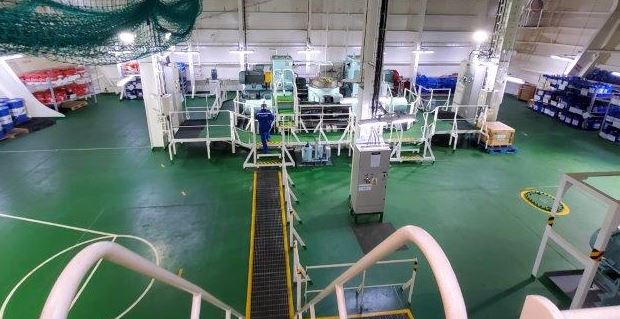
Check Point
-
①Non-slip painting
-
②Handrail installing
11.8 Em'cy Fire pump
Guide to Inspection
-
SOLAS / CH II-2 / Reg 10
2.2.3.2 Requirements for the space containing the emergency fire pump
2.2.3.2.1 Location of the space
The space containing the fire pump shall not be contiguous to the boundaries of machinery spaces of category A or those spaces containing main fire pumps. Where this is not practicable, the common bulkhead between the two spaces shall be insulated to a standard of structural fire protection equivalent to that required for a control station in regulation 9.2.3.3. Go!IACS UI SC 114
2.2.3.2.2 Access to the emergency fire pump
No direct access shall be permitted between the machinery space and the space containing the emergency fire pump and its source of power. When this is impracticable, the Administration may accept an arrangement where the access is by means of an airlock with the door of the machinery space being of A-60 class standard, and the other door being at least steel, both reasonably gastight, self-closing and without any hold back arrangements. Alternatively, the access may be through a watertight door capable of being operated from a space remote from the machinery space and the space containing the emergency fire pump and unlikely to be cut off in the event of fire in those spaces. In such cases, a second means of access to the space containing the emergency fire pump and its source of power shall be provided.
2.2.3.2.3 Ventilation of the emergency fire pump space
Ventilation arrangements to the space containing the independent source of power for the emergency fire pump shall be such as to preclude, as far as practicable, the possibility of smoke from a machinery space fire entering or being drawn into that space.
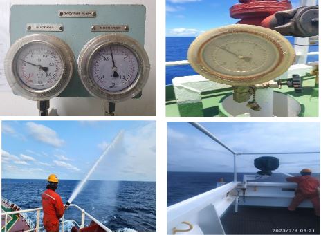
Check Point
-
①Starting<br>- not less than Six times / 30min & not less than Twice / Initial 10 min<br>- Precaution for operation with Lower draft<br>- Suction operation ( including Vacuum pump)<br>- Leakage inspection
-
②Suction pressure
-
③Two jets of water(Fore/Bridge)
12. Engine Room (Engineers)
12.1 ECR
Guide to Inspection
-
SOLAS / CH II-1 / Reg. 31.5.3
.3 Where the main propulsion and associated machinery, including sources of main electrical supply, are provided with various degrees of automatic or remote control and are under continuous manual supervision from a control room, the arrangements and controls shall be so designed, equipped and installed that the machinery operation will be as safe and effective as if it were under direct supervision; for this purpose regulations 46 to 50 shall apply as appropriate. Particular consideration shall be given to protect such spaces against fire and flooding.
SOLAS / CH II-1 / Reg. 41.3
3 The main switchboard shall be so placed relative to one main generating station that, as far as is practicable, the integrity of the normal electrical supply may be affected only by a fire or other casualty in one space. An environmental enclosure for the main switchboard, such as may be provided by a machinery control room situated within the main boundaries of the space, is not to be considered as separating the switchboards from the generators.
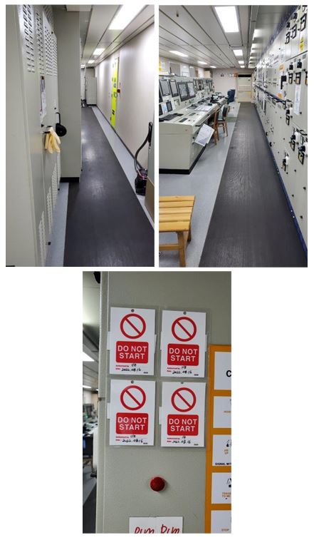
Check Point
-
①Abnormal alarm AMS
-
②Switch board Low insulation
-
③Insulation mat
12.2. Fire Detector
Guide to Inspection
-
SOLAS / CH II-2 / Reg 7
2 General requirements
2.1 A fixed fire detection and fire alarm system shall be provided in accordance with the provisions of this regulation.
2.2 A fixed fire detection and fire alarm system and a sample extraction smoke detection system required in this regulation and other regulations in this part shall be of an approved type and comply with the Fire Safety Systems Code.
2.3 Where a fixed fire detection and fire alarm system is required for the protection of spaces other than those specified in paragraph 5.1, at least one detector complying with the Fire Safety Systems Code shall be installed in each such space.
Periodically, fixed fire detectors and fire alarm systems shall be tested in accordance with MSC.1/Circ.1432 using equipment suited to the types of fires to which the detector is designed to respond.
If indicated by the manufacturer, the test protocol and specialised test equipment should be followed and used.
Spaces not covered by a fire detection system shall be covered by regular fire patrols.
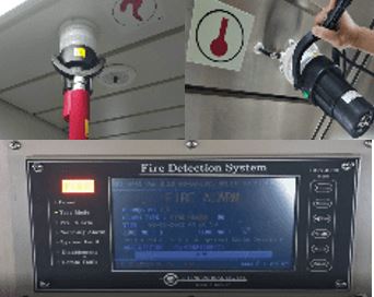
Check Point
-
①Detector Test (Thermal, Smoke)
-
②Audible/Visible alarm
-
③Check the drawing
-
④AC/DC Test procedure & understanding
12.3 Portable fire extinguisher
Guide to Inspection
-
SOLAS / CH II-2 / Reg 10.5
5 Fire extinguishing arrangements in machinery spaces
5.1 Machinery spaces containing oil-fired boilers or oil fuel units (Go! Refer to IACS UI SC30)
5.1.1 Fixed fire-extinguishing systems
Machinery spaces of category A containing oil-fired boilers or oil fuel units shall be provided with any one of the fixed fire-extinguishing systems in paragraph 4.1. In each case, if the engine and boiler rooms are not entirely separate, or if fuel oil can drain from the boiler room into the engine-room, the combined engine and boiler rooms shall be considered as one compartment.
5.1.2 Additional fire-extinguishing arrangements *
* Refer to Unified interpretation of SOLAS chapter II-2 on the number and arrangement of portable fire extinguishers on board ships (MSC.1/Circ.1275 and Corr.1).
5.1.2.1 There shall be in each boiler room or at an entrance outside of the boiler room at least one portable foam applicator unit complying with the provisions of the Fire Safety Systems Code.
5.1.2.2 There shall be at least two portable foam extinguishers or equivalent in each firing space in each boiler room and in each space in which a part of the oil fuel installation is situated. There shall be not less than one approved foam-type extinguisher of at least 135 l capacity or equivalent in each boiler room. These extinguishers shall be provided with hoses on reels suitable for reaching any part of the boiler room. In the case of domestic boilers of less than 175 kW, or boilers protected by fixed water-based local application fire-extinguishing systems as required by paragraph 5.6, an approved foam-type extinguisher of at least 135 l capacity is not required.(Replaced by Res.MSC.409(97))
5.1.2.3 In each firing space there shall be a receptacle containing at least 0.1 m³ sand, sawdust impregnated with soda, or other approved dry material, along with a suitable shovel for spreading the material. An approved portable extinguisher may be substituted as an alternative.
5.2 Machinery spaces of category A containing internal combustion machinery ( Replaced by Res.MSC.380(94))
(IACS UI SC30)
5.2.1 Fixed fire-extinguishing systems
Machinery spaces of category A containing internal combustion machinery shall be provided with one of the fixed fire-extinguishing systems in paragraph 4.1.
5.2.2 Additional fire-extinguishing arrangements*
* Refer to Unified interpretation of SOLAS chapter II-2 on the number and arrangement of portable fire extinguishers on board ships (MSC.1/Circ.1275 and Corr.1).
5.2.2.1 There shall be at least one portable foam applicator unit complying with the provisions of the Fire Safety Systems Code.
5.2.2.2 There shall be in each such space approved foam-type fire extinguishers, each of at least 45 l capacity or equivalent, sufficient in number to enable foam or its equivalent to be directed on to any part of the fuel and lubricating oil pressure systems, gearing and other fire hazards. In addition, there shall be provided a sufficient number of portable foam extinguishers or equivalent which shall be so located that no point in the space is more than 10 m walking distance from an extinguisher and that there are at least two such extinguishers in each such space. For smaller spaces of cargo ships the Administration may consider relaxing this requirement.
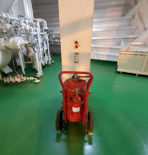
Check Point
-
①Contents replacing date <br> - Annual inspection report by service engineer<br> - [M&I Log], [History record of FFA]
-
②Working test(Sampling)
-
③Hydro test date<br> - 10 Years since the cylinder was manufactured
-
④Keep a label and tag
12.4 Emergency escape Trunk
Guide to Inspection
-
SOLAS / CH II-2 / Reg 13
4.2 Means of escape of cargo ships
4.2.3 Escape from machinery spaces other than those of category A
From machinery spaces other than those of category A, two escape routes shall be provided except that a single escape route may be accepted for spaces that are entered only occasionally, and for spaces where the maximum travel distance to the door is 5 m or less.
4.2.4 Inclined ladders and stairways ( Added by Res.MSC.365(93))
For ships constructed on or after 1 January 2016, all inclined ladders/stairways fitted to comply with paragraph 4.2.1 with open treads in machinery spaces being part of or providing access to escape routes but not located within a protected enclosure shall be made of steel. Such ladders/stairways shall be fitted with steel shields attached to their undersides, such as to provide escaping personnel protection against heat and flame from beneath.
4.2.5 Escape from machinery control rooms in machinery spaces of category "A" ( Added by Res.MSC.365(93))
For ships constructed on or after 1 January 2016, two means of escape shall be provided from the machinery control room located within a machinery space. At least one of these escape routes shall provide a continuous fire shelter to a safe position outside the machinery space.
Refer to MSC.1/Circ.1511 UNIFIED INTERPRETATIONS OF SOLAS REGULATIONS II-2/9 AND II-2/13
4.2.6 Escape from main workshops in machinery spaces of category "A" ( Added by Res.MSC.365(93))
For ships constructed on or after 1 January 2016, two means of escape shall be provided from the main workshop within a machinery space. At least one of these escape routes shall provide a continuous fire shelter to a safe position outside the machinery space.
In the event of the engine room being filled with smoke, even light smoke, the escape routes, and doors from the engine room may be obscured and therefore they should be more clearly indicated. The crew cannot see a white door against a white bulkhead. Whatever paint is used it should be a water-based paint rather than an oil-based paint, so as not to affect the
properties of the class ‘A’ fire doors that are always fitted to the engine room exits.
Pad eye, shackle, single block, rope, and harness should be provided for lifting an incapacitated person from engine room.
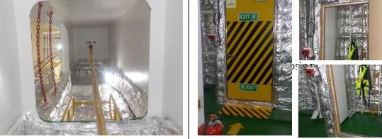
Check Point
-
①Insulation condition
-
②Entrance door <br> - Self closing fire door <br> - No Hook and No wood plate<br>* Perfect Tight condition and Closing force adjustment
-
③Em’cy lighting
-
④Highlight marking (fluorescent paint or tape)
-
⑤Flashlight, safety harness (Photo: Light and overall condition)
12.5 Quick Closing / Shut-off valve
Guide to Inspection
-
SOLAS / CH II-2 / Reg 4.2.3
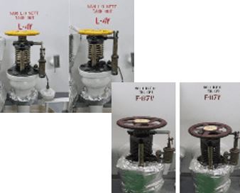
Check Point
-
①Working condition
-
②Any paralyzing by the bolt and Wood Wedge
-
③Fuel oil tank quick closing valve condition
12.6 Insulation, Ragging
Guide to Inspection
-
SOLAS / CH II-2 / Reg 4.2.2
2.2.6 Protection of high temperature surfaces
2.2.6.1 Surfaces with temperatures above 220 degrees C which may be impinged as a result of a fuel system failure shall be properly insulated.
2.2.6.2 Precautions shall be taken to prevent any oil that may escape under pressure from any pump, filter or heater from coming into contact with heated surfaces.
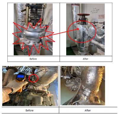
Guide to Inspection
-
① Dropping and Missing part(Refer to Fire protection plan)
-
② Hot space insulation - heated over than 220℃ by fuel line damage
-
③ Temporary repair<br>- Cementing, doubling, bending etc
-
④ Contamination or dirty rating (Evidence leaking)
-
⑤No breakaway/omission
12.7 Jacketed pipe for high pressure fuel
Guide to Inspection
-
① Missing-Installation
** MSC/Circ.1170(80)(Draft Amendments), SOLAS Reg.II-2/15.2.9 and 15.2.12
is subject to the vessel with K/L after 1992.02.01. (Engine power > 375Kw)
② Drain box alarm normal operation
③ Fuel high pressure pipe F.O leakage and locking condition
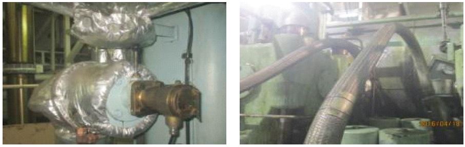
Check Point
-
①No missing part
-
②Drain box alarm
12.8 Oil filtering equipment
Guide to Inspection
-
MARPOL Annex I / CH-III / Reg 14
MEPC / 107(49)
29 Oil filtering equipment
Regs. 14.1, 14.2
Oil filtering equipment referred to in regulations 14.1 and 14.2 is a 15 ppm bilge separator and may include any combination of a separator, filter or coalescer and also a single unit designed to produce an effluent with oil content not exceeding 15 ppm.
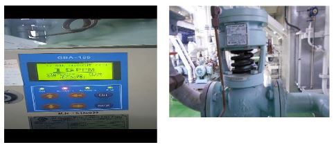
Check Point
-
①15ppm alarm (with video keeping)
-
②Auto-stop
-
③3-Way valve operation and pump operation stop
-
④Filter & Inner condition
-
⑤Use maker’s filter & spare filter<br>(Certificate ion board)
-
⑥Crew’s familiarity for equipment<br>(operating and alarm test)
-
⑦Close the discharge valve
-
⑧Shore connection(flange size)
-
⑨Operation Manual posting
-
⑩Removal of any manual valve on the sampling line
-
⑪Time synchronized (No delayed)
-
⑫Outlet pipe inside<br>(Recommends, Cleaning inside every 12months when Classification inspection request or C/E's judge)
-
⑬Display the Operation guidance
12.9 Direct line for discharging oily bilge
Guide to Inspection
-
MARPOL / Annex I / Reg. 15
D. General requirements
7 Whenever visible traces of oil are observed on or below the surface of the water in the immediate vicinity of a ship or its wake, Governments of Parties to the present Convention should, to the extent they are reasonably able to do so, promptly investigate the facts bearing on the issue of whether there has been a violation of the provisions of this regulation. The investigation should include, in particular, the wind and sea conditions, the track and speed of the ship, other possible sources of the visible traces in the vicinity, and any relevant oil discharge records.
8 No discharge into the sea shall contain chemicals or other substances in quantities or concentrations which are hazardous to the marine environment or chemicals or other substances introduced for the purpose of circumventing the conditions of discharge specified in this regulation.
9 The oil residues which cannot be discharged into the sea in compliance with this regulation shall be retained on board for subsequent discharge to reception facilities.
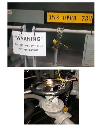
Check Point
-
①To be removed if installed
12.10 E/R floor(Cleanliness)
Guide to Inspection
-
SOLAS / CH II-2 / Reg 4
Regulation 4
Probability of ignition
1 Purpose
The purpose of this regulation is to prevent the ignition of combustible materials or flammable liquids. For this purpose, the following functional requirements shall be met:
.1 means shall be provided to control leaks of flammable liquids;
.2 means shall be provided to limit the accumulation of flammable vapours;
.3 the ignitability of combustible materials shall be restricted;
.4 ignition sources shall be restricted;
.5 ignition sources shall be separated from combustible materials and flammable liquids; and
.6 the atmosphere in cargo tanks shall be maintained out of the explosive range.
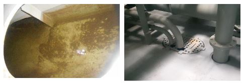
Guide to Inspection
-
①Cleaning condition
-
②E/R Floor, Bilge well inspection
-
③Oil/water leakage of Main/Aux. machineries
-
④No residual and oily rags
-
⑤No oil leaks from outer surface of welded fuel oil tanks(pin hole)
12.11 Sewage equipment
Guide to Inspection
-
MARPOL / Annex IV
1 Every ship which, in accordance with regulation 2, is required to comply with the provisions of this Annex shall be equipped with one of the following sewage systems:
.1 a sewage treatment plant which shall be of a type approved by the Administration, taking into account the standards and test methods developed by the Organization*, or
* Refer to the Recommendation on international effluent standards and guidelines for performance tests for sewage treatment plants (resolution MEPC.2(VI)), Revised guidelines on implementation of effluent standards and performance tests for sewage treatment plants adopted by the MEPC (resolution MEPC.159(55)) (see Unified Interpretation 3), or the 2012 Guidelines on implementation of effluent standards and performance tests for sewage treatment plants (resolution MEPC.227(64), as amended by resolution MEPC.284(70))
.2 a sewage comminuting and disinfecting system approved by the Administration. Such system shall be fitted with facilities to the satisfaction of the Administration, for the temporary storage of sewage when the ship is less than 3 nautical miles from the nearest land, or
.3 a holding tank of the capacity to the satisfaction of the Administration for the retention of all sewage, having regard to the operation of the ship, the number of persons on board and other relevant factors. The holding tank shall be constructed to the satisfaction of the Administration and shall have a means to indicate visually the amount of its contents.
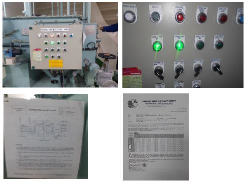
Check Point
-
①Level alarm (with Video)
-
②Pump operation<br>- Auto discharge test - Level S/W operation<br>- Air blowing"
-
③Crew’s familiarity for equipment<br> - operating and alarm test
-
④Air diffuser & circulation line
-
⑤Discharge Ratio
-
⑥Shore connection(flange size)
-
⑦Internal corrosion
12.12 Watch keeping schedules(for ship underway or at port)
Guide to Inspection
-
MLC / A2.3 10
10. Each Member shall require the posting, in an easily accessible place, of a table with the shipboard working arrangements, which shall contain for every position at least:
(a) the schedule of service at sea and service in port; and
(b) the maximum hours of work or the minimum hours of rest required by national laws or regulations or applicable collective agreements.
11. The table referred to in paragraph 10 of this Standard shall be established in a standardized format in the working language or languages of the ship and in English.
Check Point
-
①Watch keeping schedules established and posted
12.13 Familiarization with engine room machinery
Guide to Inspection
-
STCW / Section A-VIII/2 / Part 4-2
PART 4-2 - TAKING OVER THE ENGINEERING WATCH
100 Prior to taking over the engineering watch, the relieving officer shall be informed by the officer in charge of the engineering watch as to:
.1 the standing orders of the day, any special orders relating to the ship operations, maintenance functions, repairs to the ship's machinery or control equipment;
.2 the nature of all work being performed on machinery and systems on board ship, personnel involved and potential hazards;
.3 the level and condition, where applicable, of water or residue in bilges, ballast tanks, slop tanks, sewage tanks, reserve tanks and special requirements for the use or disposal of the contents thereof;
.4 any special requirements relating to sanitary system disposals;
.5 the condition and state of readiness of portable fire-extinguishing equipment and fixed fire-extinguishing installations and fire detection systems;
.6 authorized repair personnel on board engaged in engineering activities, their work locations and repair functions and other authorized persons on board and the required crew;
.7 any port regulations pertaining to ship effluents, fire-fighting requirements and ship readiness, particularly during potential bad weather conditions;
.8 the lines of communication available between the ship and shore personnel, including port authorities, in the event of an emergency arising or assistance being required;
.9 any other circumstance of importance to the safety of the ship, its crew, cargo or the protection of the environment from pollution; and
.10 the procedures for notifying the appropriate authority of environmental pollution resulting from engineering activities.
101 Relieving officers, before assuming charge of the engineering watch, shall satisfy themselves that they are fully informed by the officer being relieved, as outlined above, and:
.1 be familiar with existing and potential sources of power, heat and lighting and their distribution;
.2 know the availability and condition of ship's fuel, lubricants and all water supplies; and
.3 be ready to prepare the ship and its machinery, as far as is possible, for stand-by or emergency conditions as required.
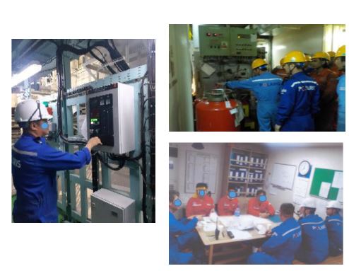
Check Point
-
①Familiarization with Engine Room Machinery<br>- operations, maintenances, and any relevant record
12.14 Water mist fire fighting system
Guide to Inspection
-
SOLAS CH II-2, Reg 10
Machinery spaces onboard vessels are at high risk of fires.
SOLAS requires fixed fire-extinguishing systems for engine and boiler rooms (Reg. II-2/10.5).
Since 2002, engine rooms above 500 m³ in volume must also be protected by a fixed water-based or equivalent local application fire-fighting system (Reg. II-2/10.5.6).
Water mist systems are commonly used for this purpose.
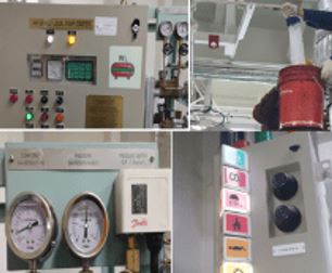
Check Point
-
①Motor, valve & nozzle operation
-
②Inspection record (If possible, keep a video)
-
③familiarization
-
④Confirm no blocking by obstruction
12.15 Electric Panel
Guide to Inspection
-
SOLAS / CH II-1 / Reg 45
2 Main and emergency switchboards shall be so arranged as to give easy access as may be needed to apparatus and equipment, without danger to personnel. The sides and the rear and, where necessary, the front of switchboards shall be suitably guarded. Exposed live parts having voltages to earth exceeding a voltage to be specified by the Administration shall not be installed on the front of such switchboards. Where necessary, nonconducting mats or gratings shall be provided at the front and rear of the switchboard.
Check Point
-
①Insulation Mat in position
-
②Elec. Insulation (Low insulation)
12.16 Emergency Bilge Suction
Guide to Insepction
-
SOLAS CH 2-1 Reg.35-1
2.1 An efficient bilge pumping system shall be provided, capable of pumping from and draining any watertight compartment other than a space permanently appropriated for the carriage of fresh water, water ballast, oil fuel or liquid cargo and for which other efficient means of pumping are provided, under all practical conditions. Efficient means shall be provided for draining water from insulated holds.
2.2 Sanitary, ballast and general service pumps may be accepted as independent power bilge pumps if fitted with the necessary connections to the bilge pumping system.
2.3 All bilge pipes used in or under coal bunkers or fuel storage tanks or in boiler or machinery spaces, including spaces in which oil-settling tanks or oil fuel pumping units are situated, shall be of steel or other suitable material.
2.4 The arrangement of the bilge and ballast pumping system shall be such as to prevent the possibility of water passing from the sea and from water ballast spaces into the cargo and machinery spaces, or from one compartment to another. Provision shall be made to prevent any deep tank having bilge and ballast connections being inadvertently flooded from the sea when containing cargo, or being discharged through a bilge pump when containing water ballast.
2.5 All distribution boxes and manually operated valves in connection with the bilge pumping arrangements shall be in positions which are accessible under ordinary circumstances.
4 Cargo ships
At least two power pumps connected to the main bilge system shall be provided, one of which may be driven by the propulsion machinery. If the Administration is satisfied that the safety of the ship is not impaired, bilge pumping arrangements may be dispensed with in particular compartments.
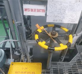
Check Point
-
①Valve Condition
-
②Valve Seal, Tag
-
③Pipe diagram and proper marking
12.17 Emergency Air compressor
Guide to Inspection
-
SOLAS / CH II-1 / Reg.34
Air pressure systems
1 In every ship means shall be provided to prevent overpressure in any part of compressed air systems and wherever water jackets or casings of air compressors and coolers might be subjected to dangerous overpressure due to leakage into them from air pressure parts. Suitable pressure relief arrangements shall be provided for all systems.
2 The main starting air arrangements for main propulsion internal combustion engines shall be adequately protected against the effects of backfiring and internal explosion in the starting air pipes.
3 All discharge pipes from starting air compressors shall lead directly to the starting air receivers, and all starting pipes from the air receivers to main or auxiliary engines shall be entirely separate from the compressor discharge pipe system.
4 Provision shall be made to reduce to a minimum the entry of oil into the air pressure systems and to drain these systems.
Check Point
-
① Air tank charging condition
-
② Running (Charging) inspection
12.18 Work shop
-
①Cleanness
-
②Garbage separation & Segregation
-
③Insulation mat
-
④Abnormal alarm AMS
-
⑤Switch board Low insulation
12.19 Emergency lighting
Guide to Inspection
-
SOLAS / CH-II-1 / Reg.43
2 The electrical power available shall be sufficient to supply all those services that are essential for safety in an emergency, due regard being paid to such services as may have to be operated simultaneously. The emergency source of electrical power shall be capable, having regard to starting currents and the transitory nature of certain loads, of supplying simultaneously at least the following services for the periods specified hereinafter, if they depend upon an electrical source for their operation :
2.1 For a period of 3 h, emergency lighting at every muster and embarkation station and over the sides as required by regulations III/11.4 and III/16.7.
2.2 For a period of 18 h, emergency lighting :
.1 in all service and accommodation alleyways, stairways and exits, personnel lift cars and personnel lift trunks ;
.2 in the machinery spaces and main generating stations including their control positions ;
.3 in all control stations, machinery control rooms, and at each main and emergency switchboard ;
.4 at all stowage positions for firemen's outfits ;
.5 at the steering gear ;
.6 at the fire pump referred to in paragraph 2.5, at the sprinkler pump, if any, and at the emergency bilge pump, if any, and at the starting positions of their motors ; and
.7 in all cargo pump-rooms of tankers constructed on or after 1 July 2002.
Check Point
-
①Working Test
-
②No damage (Cover)
12.20 Alarms
Guide to Inspection
-
SOLAS / Ch II-1 / Reg. 51
Alarm system
1 An alarm system shall be provided indicating any fault requiring attention and shall:
.1 be capable of sounding an audible alarm in the main machinery control room or at the propulsion machinery control position, and indicate visually each separate alarm function at a suitable position;
.2 have a connexion to the engineers' public rooms and to each of the engineers' cabins through a selector switch, to ensure connexion to at least one of those cabins. Administrations may permit equivalent arrangements;
.3 activate an audible and visual alarm on the navigating bridge for any situation which requires action by or attention of the officer on watch;
.4 as far as is practicable be designed on the fail-to-safety principle; and
.5 activate the engineers' alarm required by Regulation 38 if an alarm function has not received attention locally within a limited time.
2.1 The alarm system shall be continuously powered and shall have an automatic change-over to a stand-by power supply in case of loss of normal power supply.
2.2 Failure of the normal power supply of the alarm system shall be indicated by an alarm.
3.1 The alarm system shall be able to indicate at the same time more than one fault and the acceptance of any alarm shall not inhibit another alarm.
3.2 Acceptance at the position referred to in paragraph 1 of any alarm condition shall be indicated at the positions where it was shown. Alarms shall be maintained until they are accepted and the visual indications of individual alarms shall remain until the fault has been corrected, when the alarm system shall automatically reset to the normal operating condition.
SOLAS / Ch II-1 / Reg. 52
Safety systems
A safety system shall be provided to ensure that serious malfunction in machinery or boiler operations, which present an immediate danger, shall initiate the automatic shut-down of that part of the plant and that an alarm shall be given. Shut-down of the propulsion system shall not be automatically activated except in cases which could lead to serious damage, complete breakdown, or explosion. Where arrangements for overriding the shut-down of the main propelling machinery are fitted, these shall be such as to preclude inadvertent operation. Visual means shall be provided to indicate when the override has been activated.
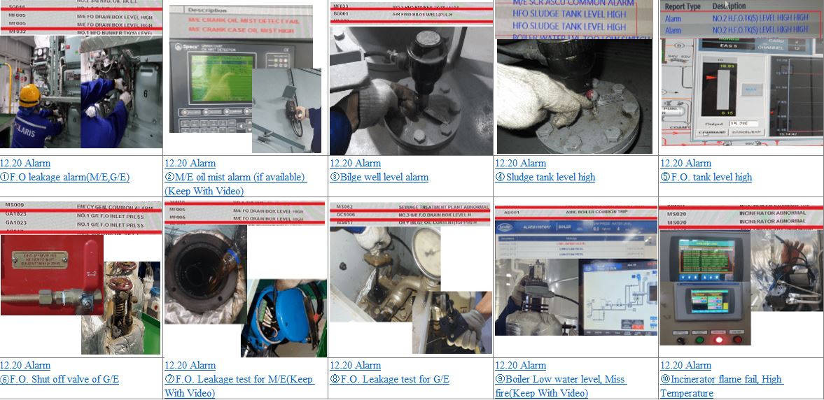
Check Point
-
①F.O leakage alarm(M/E,G/E)
-
②M/E oil mist alarm (if available) (Keep With Video)
-
③Bilge well level alarm
-
④Sludge tank level high
-
⑤F.O. tank level high
-
⑥F.O. Shut off valve of G/E
-
⑦F.O. Leakage test for M/E(Keep With Video)
-
⑧F.O. Leakage test for G/E
-
⑨Boiler Low water level, Miss fire(Keep With Video)
-
⑩Incinerator flame fail, High Temperature

")


