")


Information
-
Document No.
-
Audit Title
-
Client / Site
-
Conducted on
-
Prepared by
-
Location
-
Personnel
-
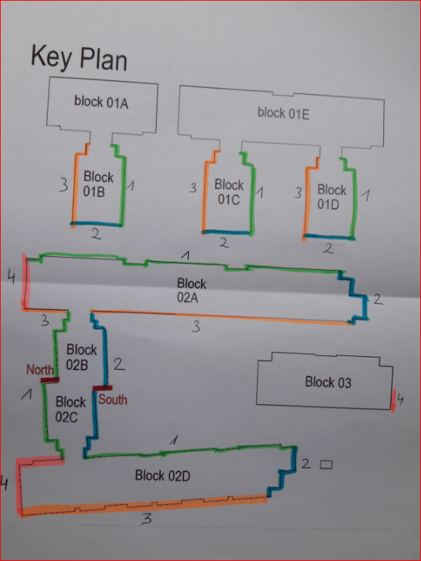
BEFORE YOU START THIS REPORT, REFERENCE MUST BE MADE TO THE PROJECT ELEVATION LAYOUT SKETCH DETAILING THE EXACT LOCATION(S) INSPECTED.
Rules of WIR and Progress Reporting:
1. All reports need to be in for the dates that have been agreed on the Reporting Schedule. PM must contact HSEQ Department if there will be a delay.
2. The elevation inspected must be clearly identified using the Elevation Layout Sketch produced by the CM of the project, clearly identifying each elevation and floor. Ideally, there should be a separate Report for each elevation, however on smaller works, a single report for more than one elevation is acceptable.
3. Each report should include a description of the type of system / works undertaken.
4. Reports should also include quality issues not caused by CF, but which impact on our works.
5. Refer to recent Supplementary Quality Reports before starting.
6. We have issued standard Detail drawings reference numbers D01, D02, and so on. These need to be referred to throughout WIR and clearly show what is required. Only “Clarke” Drawings should be followed.
7. All reports must be up-loaded to Clarkes Server or emailed to HSEQ Dept before deadline.The next report that will follow must show how the errors were rectified. If improvement was not possible, e.g.: due to soft ground/lack of access, it needs to be described/explained. The answers column still needs to be highlighted red. However, if the error was rectified the section should be changed to green. The comment section is to be used for explanations of how and when error was rectified.
8. If project manager has found an error during the assessment, it must be noted and fixed before consecutive stages of works progresses, eg: CP board cannot start before Metsec sub frame is properly fixed. Quality Control Manager cannot accept the next WIR report until everything is fixed and up to date on the previous report. This is to make sure that all errors are corrected, and there are no error omissions.
9. Reports need to be genuine and relevant.
10. It is important that reports always have any delay events recorded.
11. All completed reports must be sent to head office, client and subcontractor. -
Fire Strategy
I. During Sub frame /Cement Board Installation.
1. The applicator must be given all detailed drawings, levels, locations of firebreaks.
2. Mineral filler must be fitted between floor slab and cement board? (MClarke WIR Reference Booklet. Draw. No. D01)
II. Rain screen cladding
1. Vertical and horizontal fire barriers must be fitted at correct locations as per fire strategy drawings.
2. Fire barriers of correct depth must be fitted with recommended fixings at specified centres.
3. Fire breaks must be mitred at the edges/corners of the façade so as to provide continuity of intumescent layer.
4. Intumescent Firebreaks must be fitted properly? (Suitable spikes must be used and fitted at correct centres). Fire brakes must be fitted firmly and stably after being cut in location of rails and at mitred corners.
5. The correct number of stainless steel fire pins has to be used. ( minimum one per board or as per specified in the Fire Strategy)
6. Fire breaks must be fitted around windows.(only applicable when specified in the Fire Strategy and Design)
7. Intumescent fire breaks must be maintained from the back surface of the panels at correct distance.
8. Fire breaks with intumescent layer must be fitted the way to allow unimpeded contact with the rear surface of the panel. (on cassette/tray system fire breaks must be installed in those locations where intumescent layer will be allowed to expand without any restrictions) -
Elevations assessed & works completed
-
1. Have all REDs/ Issues on last set of reports been properly closed out before proceeding with rest of works?<br>
-
Add media
-
Completed by subcontractors.
PRE START CHECKS
-
1. Has the appointed sub-contractor read, understood and been given a copy of relevant parts of WIR?
-
2. Have the operatives been given a relevant and up to date drawings and details to complete the works.?<br><br><br>
-
3. Have all measuring tapes being used by Subcontractors been calibrated? (Sticker with Clarke facades logo must be attached to all tapes that have been calibrated)<br>
-
4. Has the most recent Drawing Issue Sheet been displayed in the place where all site personnel can see it ?<br>
E. BREATHER MEMBRANE & EPDM
-
1. Are EPDM's correctly installed to window interfaces.?<br><br>
-
Add media
-
2. Has EPDM been installed to all vents, rain water pipes, louvers bracket ?
-
Add media
-
3. Has the breather membrane been dressed out and over horizontal flashings, pods, rain water pipes? Has breather membrane been sealed and taped with Dafa tape
-
Add media
-
4. Has the correct and specified breather membrane been installed?<br><br>
-
Add media
-
5. Has breather membrane been taped fully at vertical joints and overlapped at dotted line, and tagged at appropriate spacing?<br><br><br>
-
Add media
-
6. Has the breather membrane been taped to and around all openings protrusions, as specified on the Reference Drawing D 03 (see MClarke reference booklet)<br><br>
-
Add media
-
7. Has interface between Roofing Membrane & Breather Membrane been sealed with Dafa tape?<br><br><br>
-
Add media
F. SUBFRAME SETTINGS (Tray-panel only)
-
1. Have subframe helping hand brackets been installed in accordance with the subframe layout drawings?<br>
-
Add media
-
2. Have brackets been fixed at specified locations?<br><br><br>
-
Add media
-
3. Have helping hand brackets been fixed to the substrate with specified number of anchors.?<br><br><br>
-
Add media
-
4.Have specified brackets with thermal pads been fitted to the substrate at specified fixing centres ?<br>
-
Add media
-
5. Have L/T-rails been fixed into brackets through specified holes, so as to permit thermal movement of the rails. Has specified number of fixings been used?<br>
-
Add media
-
6. Have Fixed and Gliding Points been installed as per Subframe Drawings?<br>
-
Add media
-
7. Have rails been set out in accordance with deflection point location?<br>
-
Add media
-
8. Is the top and bottom of the rails overhanging no more than it is indicated on the rail setting drawing?<br>
-
Add media
-
9. Has the Project Manager checked the level with string line or laser?<br>
-
Add media
G. INSULATION/TAPING & FIRE BARRIERS
-
1.Has insulation been fitted as tight as possible, has silver tape been applied as per specification/detailed drawings? <br>
-
Add media
-
2.Have all outlets, brackets, vents, edges of insulation boards, joints etc. been taped up with silver tape?<br><br><br><br><br>
-
-
3.Has proper pattern of mechanical fixing been used? Have fixings been foil taped? (Reference, see Figure 7, M.Clarke Guidance Booklet.)<br><br>
-
Add media
-
4.Have the correct number of stainless steel fire pins been installed ?(minimum one per board or as specified in the Fire Strategy - Pin to be left exposed /uncovered)<br><br><br><br><br><br><br>
-
-
5.Have vertical and horizontal fire barriers been fitted at correct locations as per fire strategy?<br><br>
-
Add media
-
6.Have fire breaks been mitered at the edges/corners of the facade so as to provide continuity of intumescent layer?<br>
-
Add media
-
7. Have Intumescent firebreaks been fitted correctly? (suitable spikes been used and fitted at correct centres). Are fire breaks fitted firmly and stably after being cut in location of rails and at mitred corners?
-
Add media
-
8. Have fire breaks been fitted around windows ? (only applicable when specified in the Fire strategy/Design)
-
Add media
-
9. Have fire barriers with Intumescent Strip been fitted as per design and manufacturer's detail?
-
Add media
D. FLASHING / PODS / CILL CORNER TRIMS
-
1. Are cills, pods and flashings installed to the correct details of the design? Thickness, colour and depth?<br><br>
-
Add media
-
2. Are Cills pods and flashings of proper quality and shape?<br>
-
Add media
K. Tray panels.
-
1. Have tray panels been fixed at correct locations? <br><br><br>
-
Add media
-
2. Has Intumescent fire break been maintained away at correct distance from the back surface of the panels?<br><br><br><br><br>
-
Add media
-
3. Have gaps been maintained between wall planks as per detailed drawing?<br><br>
-
Add media
-
4. Has Flymesh been fitted as per detailed drawings?<br><br><br>
-
Add media
-
5. Has protective film been removed immediately and panels cleaned down?<br><br><br>
-
Add media
J. CAPPING
-
1. Has suitable and specified plywood been used? (Marine plywood must be used in all location where there is a damp, condensation risk)(Plywood by others - TBC)<br><br>
-
Add media
-
2. Has plywood been covered with breather membrane or bituminous felt as per detailed drawing?<br><br>
-
Add media
-
3. Have proper fixings been used? (It must be remembered that fixings have to be in superior anti bi-metal corrosion quality to the elements which are fastened by the fixings, e.g. Zinc coated (galvanised) steel fixings can not be used for fixing aluminium elements. It most situations stainless steel would be the safest option).<br><br>
-
Add media
-
4. Have specified support brackets & butt-strapp been fitted at 3 degree fall?. Were specified fixings used?<br>
-
Add media
-
5. Has capping been securely fixed to the bracket, has proper number of fixing been used, as per drawings/specification?<br>
-
Add media
-
6. Has proper butt-strapp, compriband and sealing been used ?
-
Add media
-
7. Are capping set to a consistent and even horizontal line?<br>
-
Add media
DOMUS WIR
-
1. Have Domus completed and submitted their own WIR?<br><br>
Inspection Results
-
Site notes.
-
Add media
-
Signed off by the Main Contractor representative.
-
Signed off by the subcontractor's representative.
-
Signed off by the Project Manager
-
Should you have any enquiries regarding this inspection report please contact M Clarke & Sons on 02825822500.

")
